FEM Finite Element Method:
Breaks large complex geometries into small connected elements in order to analyze things like strength properties.
Connect nodes with springs:
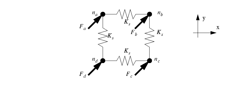
Simple linear spring force:

Work = Force that causes something to move a distance "dx"
W = Fdx = (kx)dx = 1/2 kx^2
Work of a force "F" is equal to the change in energy of a particle. Using the chain rule:

Simple Stress Strain diagram:

Nothing should be designed to operate outside of it's elastic region, and...
materials behave like simple linear springs within their elastic region.


Some example problems relating Young's Modulus to spring forces:
https://notendur.hi.is/eme1/skoli/edl_h05/masteringphysics/11/youngsModulus.htm
Failure Criteria:
von Mises criterion
- reasonable estimation of fatigue failure, especially in cases of repeated tensile and tensile-shear loading
- states that failure occurs when the energy of distortion reaches the same energy for yield/failure in uniaxial tension. Mathematically, this is expressed as,

principle stresses:

http://demonstrations.wolfram.com/MohrsCircleAndFailureCriterionForPlanarStressStates/
Review Mechanics of Materials notes:
http://engr1304.blogspot.com/2014/03/mechanics-of-materials.html
Structural integrity
- the ability of a structure to support a designed load without bending, collapsing, or breaking
Structural failure
- created when the material is stressed to its strength limit, thus causing fracture or excessive deformations.
Common types of failure:
1. Fracture:

Brittle vs. Ductile


(a) Very ductile, soft metals (e.g. Pb, Au) at room temperature, other metals, polymers, glasses at high temperature.
(b) Moderately ductile fracture, typical metals
(c) Brittle fracture, cold metals and ceramics.

*brittle fracture → rapid run of cracks through stressed material.
*very little plastic deformation
*No warning → worst type of fracture
*Amorphous microstructures (glass) produce shiny brittle fracture surfaces

In crystalline materials:
transgranular fracture - travels through the grain of the material
intergranular fracture - crack traveling along the grain boundaries
2. deformation


- object returns to its original shape
- Not permanent
Plastic Deformation:
Plastic Deformation:
- object becomes permanently deformed
3. Fatigue
The weakening of a material caused by repeatedly applied loads.
* microscopic cracks form around small discontinuities at the surface & near grain boundaries.
* cracks eventually reaches a critical size, then suddenly propagates through the remainder of the solid.

Fatigue life depends on:
- Temperature
- surface finish
- atomic microstructure
Things to avoid:
Sharp corners & bends - make everything smooth!
Example: 90° corner:
Use the probe to point out where the max stress is:

Same loading force, comparison of max stress with and without fillet:


1.411 vs. 0.58 → stress along 90° corner is ~ 2.5 times larger than the stress along the fillet.
Find where stress is concentrating on your bridge for various loading conditions, then redesign joints to more homogeneously distribute the load.
~~~~~~~~~~~~~~~~~~~~~~~~~~~~~~~~~
Fatigue rules of thumb:
Design Criteria:
Localized failure should not cause immediate or even progressive collapse of the entire structure.


Test for "critical" spots on your bridge.
Run a FEA sim where you apply a forces to critical spots (at supports and joints).
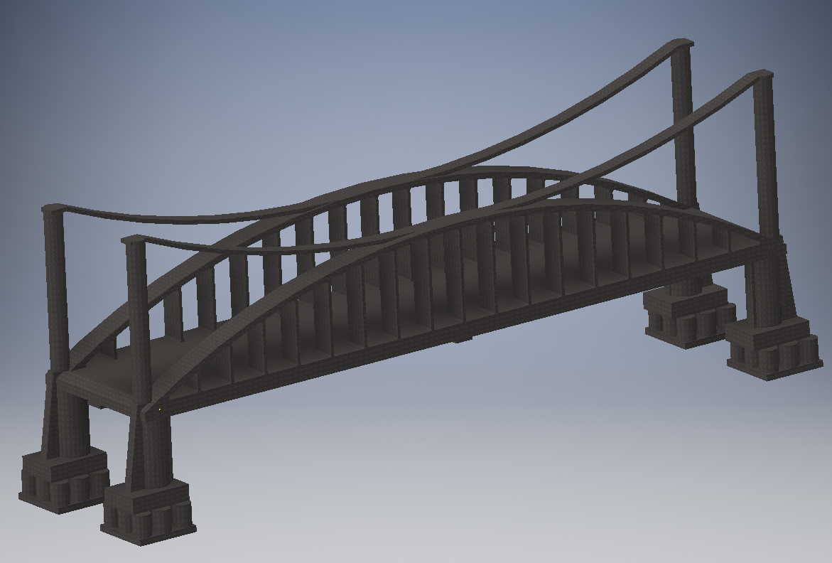
Bridges!


Create a bridge in Inventor
**Make this as one single part rather than an assembly. This will make your first attempt at FEA simpler. We will do more with constraints on our next project.


Environment → Stress analysis


Assign a material to your bridge:

Apply fixed constraints:


Add mesh
Play around with the mesh settings, create a tighter mesh in high stress areas. Update the mesh by right clicking on the red lightning bolt in your files.

Do the stress analysis!
Generate a report
Experiment with the probes
Investigate different directions of stress and strain


Civil ENGR & materials design unit
Bridge Project:
* Create Bridge (20 points)
* Apply four different loads (20 points)
* Re-design Bridge to better support above loads (20 points)
* Compare 3 different building materials. (20 points)
Bridge Report and Presentation:
*Create a ppt to present your bridge, and bridge modifications to the class (20 points)
~~~~~~~~~~~~~~~~~~~~~~~~~~~~
1. Choose a real bridge to re-create and do a stress analysis on.
- your recreation will not be exact, but you should use the general form & dimensions of an existing bridge.
____/20 points for bridge


2. Apply 3 different loading conditions
(____/ 20 points)
Loading Condition #1:
Assume the average person weighs about 150 pounds and occupies ~ 2.5 square feet in a crowd...


Loading Condition #2:
Approximate wind loads with this simple formula:
Wind pressure (Psf) = .00256 x V^2
V = wind speed in mph (use a worst case scenario of 200 mph → 102.4 lbs/sq ft)
Wind Load (Force) = Area * wind pressure * drag coefficient
Drag coefficient estimates:
1.2 for long cylinder tubes
.8 for short cylinders,
2.0 for long flat plates
1.4 for shorter flat plates
http://www.wikihow.com/Calculate-Wind-Load
http://ascelibrary.org/doi/abs/10.1061/%28ASCE%29BE.1943-5592.0000316?journalCode=jbenf2
Apply the wind force horizontally to your bridge.
Loading Condition #3
Choose the worst-case scenerio road train, get weights/lengths off of the wiki article:
http://en.wikipedia.org/wiki/Road_train


Loading condition #4: Car Crash!
What happens to your bridge if a semi-truck carrying explosives collides with and takes out one of the main supports on your bridge?
Save your bridge under a new name.
Simulate the car crash by removing a chunk of your main support.
Apply a small load to the bridge and see what happens.
Extra Credit -
What other horrible, but not completely impossible, scenarios can you think of? A good engineer does not design for average working conditions - you have to imagine up the worst case scenarios!
3. Redesign part of your bridge to better support each of the above loading conditions.


4. Show results for 3 different building materials.
Concrete
Steel - compare different types
http://en.wikipedia.org/wiki/I-beam

Use the snipping tool to capture screen shots of your bridge. Create power point slides comparing different design modifications, different materials, and different loads for your bridge.


Modal Analysis
Earthquake? Wind? Vibrating machinery? Vibrating cars & trucks?
Modal Analysis solves for natural vibrational tendencies of a structure in the form of mode shapes and frequencies.

Try just applying one fixed constraint, and then run the simulation without any other applied forces.
Use the animate tool to watch it vibrate!

Display the position of your center of gravity, and notice the influence of the center of gravity on the vibrational patterns in your bridge:
View → Center of Gravity


Notice how everything vibrates around the center of gravity.

Think about the main causes of bridge failure, and then decide how to modify your bridge to avoid these types of failures.
Find the mass, volume, center of mass etc. of your part:


The larger the volume, the more expensive it is to make.
What on your bridge is over-designed? Where can you remove a little bit of material to reduce costs?
What on your bridge is over-designed? Where can you remove a little bit of material to reduce costs?


No more red!
