
"Vasa set sail on her maiden voyage on August 10, 1628. At the time, she was the most powerfully armed warship in the world, with 64 bronze cannons.
Twenty minutes into her journey, the ship was hit by two strong winds. It heeled to port, water gushed in, and the ship sank less than a mile into the journey.
Thirty people died.
"We have, over the last three years, measured every single piece of the wood in the ship," says Hocker. "If we want to understand how the ship was built, that's what it takes."
Hocker's meticulous measurements paid off. They gave him fresh insight into what made the Vasa unstable.
For one thing, the ship was asymmetrical, more so than most ships of the day.
Why was the ship so lopsided?
While examining the ship, Hocker discovered four rulers the workmen had used. Those rulers were based on different standards of measurement at the time.
Two were in Swedish feet, which were divided into twelve inches. The other two were in Amsterdam feet, which had eleven inches in a foot. So each carpenter had used his own system of measurement.
"When somebody tells him, make that thing four inches thick, his four inches is not going to be the same as the next guy's four inches," says Hocker. "And you can see those variations in the timbers, as well."
Moral of the story, it pays to pay attention to your units, measure and create everything as exactly as you can! (Warning: If your original drawings were not constructed exactly, it is going to show up when you start trying to dimension everything.)
Skim through chapter 6
Clarity:
- Avoid clutter, use the minimum number of dimensions.
- Dimensions should not overlap or interfere with drawn object.
- Units are provided in title block, not in drawing.
- Use consistent font and spacing.
- Place dimensions outside of views rather than in the drawing object itself.
- Place dimensions between views.
- Do not dimension to hidden lines or T joints.
- Use extension lines for angled features.
Dimensions are drawn with thin, dark lines (0.25mm)
First - draw something to try out all of the dimension tools with. Choose a ws out of the book, or create your own 3D object. Your object should have a variety of different shapes. (Circles, rectangles, slanting surface, etc.)

Use the "VIEWBASE" command, and place your object in the layout area with a title block.

Create all of your dimensions in Layout space → Paper (so you don't have to reformat all your text sizes later)

- Create a Layer for dimensions if you do not already have one, and create all of your dimensions in this layer.

type "DIMSTYLE" into the command line, or click on "Manage Dimension Styles" in the annotate tab:

Click "new" or "modify"
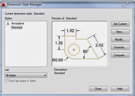
You can save your dim settings for future use.
Set your precision:
This is how many significant figures will show up on your dimensions.

Set your text height, alignment, placement, etc.

Set your arrow size to match your text size.

Set the position of your text and arrows:

Go through the rest of the settings in the dimension style menu.
Hit "OK" then "Set Current"

Note:
You will probably have to come back to the dimensions style manager a few times before you get everything set up correctly. Try out a few dimensions, see how they look, keep modifying your dimstyle until everything is appropriately sized.
Open up your Annotate tab, and have a look around.

Some common dimensioning commands:
DIMLINEAR - for horizontal and vertical measurements.
Click "new" or "modify"
You can save your dim settings for future use.
Set your precision:
This is how many significant figures will show up on your dimensions.

Set your text height, alignment, placement, etc.

Set your arrow size to match your text size.

Set the position of your text and arrows:

Go through the rest of the settings in the dimension style menu.
Hit "OK" then "Set Current"

Note:
You will probably have to come back to the dimensions style manager a few times before you get everything set up correctly. Try out a few dimensions, see how they look, keep modifying your dimstyle until everything is appropriately sized.
Open up your Annotate tab, and have a look around.
Some common dimensioning commands:
DIMLINEAR - for horizontal and vertical measurements.
DIMCONTINUE - to continue drawing linear dims that are lined up with previous dims

DIMALIGNED - for slanting surfaces

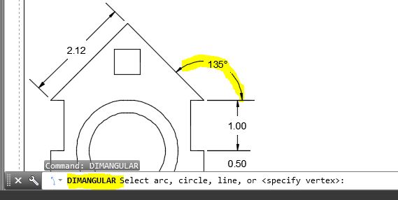
DIMANGULAR - for labeling angles

DIMRADIUS -
DIMDIAMETER -
rule of thumb - use radius when arc is less than 180°, and diameter when arc is larger than 180°.
TEXTEDIT - to add additional notes to your dimensions such as "6 PL" or 6 places, and THRU - denotes this hole goes all the way through etc.


DIMANGULAR - for labeling angles
DIMRADIUS -
DIMDIAMETER -
rule of thumb - use radius when arc is less than 180°, and diameter when arc is larger than 180°.
TEXTEDIT - to add additional notes to your dimensions such as "6 PL" or 6 places, and THRU - denotes this hole goes all the way through etc.

DIMARC: Arc length dimensions measure the distance along an arc or polyline arc segment. The extension lines of an arc length dimension can be orthogonal or radial. An arc symbol is displayed either above or preceding the dimension text.

DIMCENTER -
Creates the center mark of circles and arcs.

DIMORDINATE: (X,Y) (15, 12.5)
UCS - User Coordinate System. Define where (0,0) is on your object, then use DIMORDINATE to measure points from your UCS


DIMBASELINE:
First, select dimlinear, dimangular, etc.as your baseline, then add additional dimensions.
First, select dimlinear, dimangular, etc.as your baseline, then add additional dimensions.

DIMCONTINUE
Automatically continues creating additional dimensions from the last linear, angular, or ordinate dimension created, or from a selected extension line. The dimension lines are lined up automatically.
Automatically continues creating additional dimensions from the last linear, angular, or ordinate dimension created, or from a selected extension line. The dimension lines are lined up automatically.

DIMSPACE:
Adjusts the spacing between linear dimensions or angular dimensions.


DIMSPACE:
before:

after:

EXTEND: draw a construction line, use it to line up all the dims.
from:


DIMBREAK:
Breaks or restores dimension and extension lines where they cross other objects.


