Tiny House - see attachment in D2L
Blueprints
Ferro-gallate coated paper used for making copies before more conventional methods of printing were discovered.
3 main types of blueprints.
- A plan view - horizontal display of the proposed building project looking down from above.
The view is usually on a horizontal plane 30 inches (75 centimeters) above the floor.
The walls are drawn as parallel lines, which vary in width to specify their thickness. Dimensions are also provided in the space between two walls, representing the sizes of all the rooms throughout the house. You’ll also be able to see
Built-in items, such as cabinets
Finishes and construction methods

A measured drawing to scale of the layout of a floor in a building.
- Interior walls and hallways
- Kitchen, laundry, restrooms
- Windows and doors
- Appliances such as stoves, refrigerators, water heater etc.
- Fireplaces, porch,

1. Designed around the topography of the land, lot, and street.
What do you want to see when looking out of your windows?
Which side of your house is the sunny side?
2. Maximize convenience, minimize obstacles.
Unloading groceries - is the kitchen near the garage?
Dining room - is the table near the kitchen?
Laundry - is the laundry room near the bedrooms?
Closets - near front door? In master bathroom?
Bedrooms - are they secluded and private?
Stairs (two story house gives you more yard space) good location?
3. Open, or compartmentalized?
New homes are open - minimize hallways, maximize room sizes.
Loft ceilings, lots of windows, connected spaces.
4. Group bathrooms, kitchen, laundry room, bar etc. to minimize plumbing walls.
An elevation view is a vertical display of 1 side of the project, from either the north, south, east or west.
A section view is a cut-through display showing how something will be built.

Blueprint scale and units.
Map of countries that don't use the metric system....

R-Value:
Measure of thermal resistance of building. Under uniform conditions it is the ratio of the temperature difference across an insulator and the heat flux (heat transfer per unit area per unit time, ) through it or
  .
.
Bad (low R values: 1-4) created from too much glass, leaky windows/fireplace/doors, ventilation, thermal bridges etc.

Thermal bridging is created when materials that are poor thermal insulators come into contact, allowing heat to flow through the path of least thermal resistance.Above: thermal bridges at balconies - the balconies act as “cooling fins”; conducting the heat off the building and cooling the rooms adjacent to the balconies.

Steel studs - suck energy across a building (steel has high conductivity). Steel is 400 times more conductive than wood. (Have you ever seen a wood frying pan? Why not? Wood does not conduct heat.) How to insulate steel building? Insulate it around the outside - like pulling a sweater on (you don't eat the sweater, you put it on the outside of you)
U-factor or "U-value"
Overall heat transfer coefficient that describes how well a building element conducts heat.
U = k/L where k is the material's thermal conductivity and L is its thickness. Units of U are watts per meters squared kelvin, or W/m²K.
A smaller U-factor is better at reducing heat transfer.A low U value usually indicates high levels of insulation.
The higher the U value, the worse the thermal performance of the building.
Buildings are made up of many different components (consider layers in walls/floors/roofs etc). U factors predict the composite behaviour of an entire building element rather than relying on the properties of individual materials.
** U-Factor" is used in the US to express the insulation value of windows, while R-value is used for insulation in the rest of the building( walls, floors, roofs). The rest of the world generally use U-Value/U-Factor for elements of the entire building envelope: including windows, doors, walls, roof & ground slabs.
Physics:
Heat flow: warm to cold
Moisture flow: warm to cold
Moisture flow: More to less
Air flow: High pressure to low pressure
If your AC is on:
Cold inside ← warm outside
Heat and moisture flows from outside, to inside.
Example Problem:
Vinal wallpaper - does not breathe - you'll get mold behind the wallpaper.
FEMA trailers in NEw Orleans - AC with No ventilation + vinal wallpaper in a hot humid climate

Rooftop exhaust system -
http://www.youtube.com/watch?v=rkfAcWpOYAA
~~~~~~~~~~~~~~~~~~~~~~~~~~~~~~~~~~~~~~
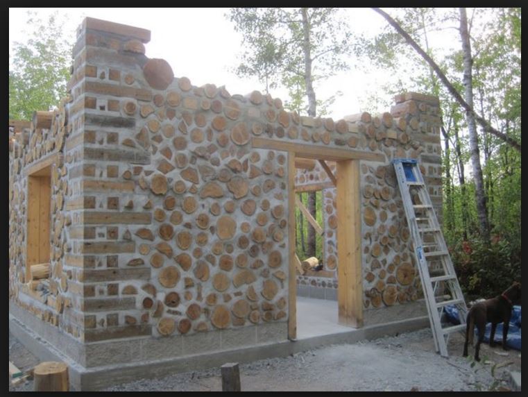
Alternative Housing:
Cordwood Construction
http://www.cordwoodconstruction.org/http://en.wikipedia.org/wiki/Cordwood_construction


Straw Bale

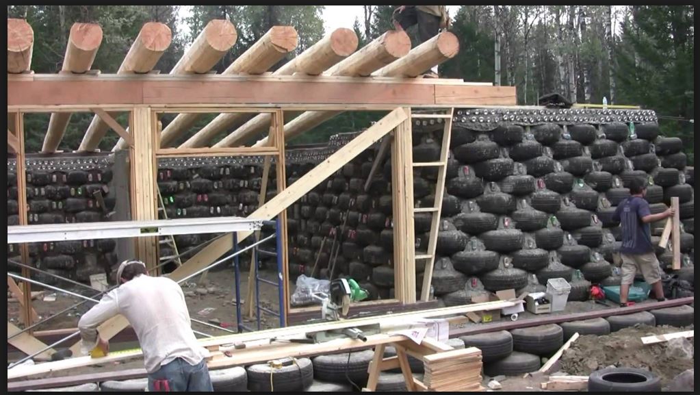
Earthship Construction -


Tree Houses


Small House movement:
http://en.wikipedia.org/wiki/Small_house_movement
Tiny House Layouts:
http://www.tinyhousedesign.com/road-limits-for-tiny-houses-on-trailers/
http://www.tumbleweedhouses.com/
Project Possibility - experiment with making a tiny house!
Create Doors:
Door swing - show the sweep of the door when opened and closed.

Need at least 2 exterior doors (2 exits for fire escape)
General rule - doors swings into a room.
Average size - used to be 32" by 6'8", now it's 3' by 6'8".
Simple Wall: two lines
Use Offset to create wall thicknesses.
Interior walls are 2x4 (or 2 by 6 for load bearing), which is 3-1/2", plus 1/2" drywall on each side. Total = 4-1/2".
Outside wall, your framing will be either 2x4 or 2x6. This gives you 3-1/2" or 5-1/2", plus 1/2" for the drywall, 1/2" for the exterior sheathing (plywood), plus a 1" airspace between the wall and the brick, and 3-5/8" for the brick. Total = 9-1/8" or 11-1/8.
Windows: sash, glass, and sill (that bulges beyond the wall)

Line thickness:
Thicker lines are more important (walls)
Thin lines (counter tops, ceiling fans) are less important.
Use different layers for different object styles, ie, one layer for walls, one layer for windows, one for furniture, etc.

Example Living Room:


Think about the furniture that needs to fit inside!
Couch sizes:
Example Dining Room:

Example Kitchen:
.jpg)

Example Bedroom:

Laundry:
Closet:
Bathroom:

Roof:
http://www.youtube.com/watch?v=81BlAB0SlA0
Roof Shapes:
http://en.wikipedia.org/wiki/List_of_roof_shapes
Stairs:
Average for residential - 11" tread, 10"run. 8" riser,

Architectural symbols There are sets of standard symbols used to represent walls, fixtures, and other parts of a building and lot. Most blueprints include a legend that explains the symbols used.


Four principal control layers for a wall:


Residential wall ↑


Roof
 Slab
Slab

How do you connect them?

Continuity of control layers is essential - connect like to like

90% of the problems happen where the roof meets a wall, or around windows, because of continuity issues.
Window: has to do everything a wall does, and more.


Roof:
http://www.youtube.com/watch?v=81BlAB0SlA0
Roof Shapes:
http://en.wikipedia.org/wiki/List_of_roof_shapes
Stairs:
Average for residential - 11" tread, 10"run. 8" riser,

Start with your floor plan.
Copy it into a new file (keep a separate file that has just your floor plan).
Extrude your walls, cut out windows and doors, then draw a poly line around the entire top of your house, and offset it 12" for the roof.


To create the entire roof, type in:
SOLIDEDIT
What do you want to see when looking out of your windows?
Which side of your house is the sunny side?
2. Maximize convenience, minimize obstacles.
Unloading groceries - is the kitchen near the garage?
Dining room - is the table near the kitchen?
Laundry - is the laundry room near the bedrooms?
Closets - near front door? In master bathroom?
Bedrooms - are they secluded and private?
Stairs (two story house gives you more yard space) good location?
3. Open, or compartmentalized?
New homes are open - minimize hallways, maximize room sizes.
Loft ceilings, lots of windows, connected spaces.
4. Group bathrooms, kitchen, laundry room, bar etc. to minimize plumbing walls.
An elevation view is a vertical display of 1 side of the project, from either the north, south, east or west.
A section view is a cut-through display showing how something will be built.
Map of countries that don't use the metric system....
- Architectural (or architect's) scale uses measurements in the English system of feet and inches. Such blueprints are drawn with a particular length set equal to 1 foot. Scales range from 1/8 inch to 3 inches equal to 1 foot.
- Engineering scale uses measurements with a scale ratio that's a multiple of 10. This can be either metric measurements, or measurements in feet and decimal parts of a foot.
- Some blueprints use an English unit scale with metric conversions; this is known as dual-dimensioning. Other blueprints use only metric units.
R-Value:
Measure of thermal resistance of building. Under uniform conditions it is the ratio of the temperature difference across an insulator and the heat flux (heat transfer per unit area per unit time,
) through it or .Bad (low R values: 1-4) created from too much glass, leaky windows/fireplace/doors, ventilation, thermal bridges etc.
- Too much glass

Red shows where most heat is lost - through the windows and roof.
Energy loss around windows can be fixed by using insulated double-pane, coated, high quality ($$$) glass.
Some high-rise windows, are as low as a R-1 or R-1.4, offering not much more insulation than no window at all. ... Engineered windows can have R-values at R-8, R-11, or R-14.
link
Rule of thumb - anything more than 30% glass is going to waste energy.
Energy efficiency concerns: - Too leaky
Buildings don't have a requirement for air tightness, but energy conservation is dependent on air tightness. - Too much air - over ventilated
- Too many thermal bridges -

Steel studs - suck energy across a building (steel has high conductivity). Steel is 400 times more conductive than wood. (Have you ever seen a wood frying pan? Why not? Wood does not conduct heat.) How to insulate steel building? Insulate it around the outside - like pulling a sweater on (you don't eat the sweater, you put it on the outside of you)
U-factor or "U-value"
Overall heat transfer coefficient that describes how well a building element conducts heat.
U = k/L where k is the material's thermal conductivity and L is its thickness. Units of U are watts per meters squared kelvin, or W/m²K.
A smaller U-factor is better at reducing heat transfer.A low U value usually indicates high levels of insulation.
The higher the U value, the worse the thermal performance of the building.
Buildings are made up of many different components (consider layers in walls/floors/roofs etc). U factors predict the composite behaviour of an entire building element rather than relying on the properties of individual materials.
** U-Factor" is used in the US to express the insulation value of windows, while R-value is used for insulation in the rest of the building( walls, floors, roofs). The rest of the world generally use U-Value/U-Factor for elements of the entire building envelope: including windows, doors, walls, roof & ground slabs.
Physics:
Heat flow: warm to cold
Moisture flow: warm to cold
Moisture flow: More to less
Air flow: High pressure to low pressure
If your AC is on:
Cold inside ← warm outside
Heat and moisture flows from outside, to inside.
Example Problem:
Vinal wallpaper - does not breathe - you'll get mold behind the wallpaper.
FEMA trailers in NEw Orleans - AC with No ventilation + vinal wallpaper in a hot humid climate
Rooftop exhaust system -
http://www.youtube.com/watch?v=rkfAcWpOYAA
~~~~~~~~~~~~~~~~~~~~~~~~~~~~~~~~~~~~~~
Alternative Housing:
Cordwood Construction
http://www.cordwoodconstruction.org/http://en.wikipedia.org/wiki/Cordwood_construction


Cob material:
http://en.wikipedia.org/wiki/Cob_(material)


Straw Bale

Earthship Construction -


Tree Houses


Small House movement:
http://en.wikipedia.org/wiki/Small_house_movement
Tiny House Layouts:
http://www.tinyhousedesign.com/road-limits-for-tiny-houses-on-trailers/
http://www.tumbleweedhouses.com/
Project Possibility - experiment with making a tiny house!
Create Doors:
Door swing - show the sweep of the door when opened and closed.
Need at least 2 exterior doors (2 exits for fire escape)
General rule - doors swings into a room.
Average size - used to be 32" by 6'8", now it's 3' by 6'8".
Simple Wall: two lines
Use Offset to create wall thicknesses.
Interior walls are 2x4 (or 2 by 6 for load bearing), which is 3-1/2", plus 1/2" drywall on each side. Total = 4-1/2".
Outside wall, your framing will be either 2x4 or 2x6. This gives you 3-1/2" or 5-1/2", plus 1/2" for the drywall, 1/2" for the exterior sheathing (plywood), plus a 1" airspace between the wall and the brick, and 3-5/8" for the brick. Total = 9-1/8" or 11-1/8.
Windows: sash, glass, and sill (that bulges beyond the wall)
Line thickness:
Thicker lines are more important (walls)
Thin lines (counter tops, ceiling fans) are less important.
Use different layers for different object styles, ie, one layer for walls, one layer for windows, one for furniture, etc.
Example Living Room:
Couch sizes:
Example Dining Room:
Example Kitchen:
Example Bedroom:
Laundry:
Closet:
Bathroom:
Roof:
http://www.youtube.com/watch?v=81BlAB0SlA0
Roof Shapes:
http://en.wikipedia.org/wiki/List_of_roof_shapes
Stairs:
Average for residential - 11" tread, 10"run. 8" riser,

Architectural symbols There are sets of standard symbols used to represent walls, fixtures, and other parts of a building and lot. Most blueprints include a legend that explains the symbols used.
How to build the perfect wall:
Four principal control layers for a wall:
- a rain control layer
- an air control layer
- a vapor control layer
- a thermal control layer
Residential wall ↑
Commercial Wall ↑
Simplified wall ↓
Cladding - aesthetics, and UV protection.
Control layers OUTSIDE of structure, otherwise you trap moisture, and create mold.(Vinal wallpaper would trap moisture - use latex paint)
Structure.
Simplified wall ↓
Cladding - aesthetics, and UV protection.
Control layers OUTSIDE of structure, otherwise you trap moisture, and create mold.(Vinal wallpaper would trap moisture - use latex paint)
Structure.
Slab and roof are similar:
Structure on inside, control layers on outside.
Structure on inside, control layers on outside.
Roof
How do you connect them?
Continuity of control layers is essential - connect like to like
90% of the problems happen where the roof meets a wall, or around windows, because of continuity issues.
Window: has to do everything a wall does, and more.
Roof:
http://www.youtube.com/watch?v=81BlAB0SlA0
Roof Shapes:
http://en.wikipedia.org/wiki/List_of_roof_shapes
Stairs:
Average for residential - 11" tread, 10"run. 8" riser,
Design your roof!
Do a Google image search on different roof styles, materials, and needs for the climate you are designing for.
Do a Google image search on different roof styles, materials, and needs for the climate you are designing for.
Start with your floor plan.
Copy it into a new file (keep a separate file that has just your floor plan).
Extrude your walls, cut out windows and doors, then draw a poly line around the entire top of your house, and offset it 12" for the roof.
Copy two offset poly outlines for the top - one for molding/gutter, one to extrude a tapered roof.

Type in EXTRUDE, select offset line, use the taper angle.
Note: it will not let you extrude it all the way up...
Type in EXTRUDE, select offset line, use the taper angle.
Note: it will not let you extrude it all the way up...
To create the entire roof, type in:
SOLIDEDIT
FACE (select the top of the house)
MOVE (pick a random point way above the roof)
Shell command -
To create multiple layers within the roof, make a few copies of your 3D roof, then use different shell thicknesses, and subtract off different layers of the roof.
Do a little research on different types of roofing insulation.
Move the roof up and down until it is just above your walls - decide what type of ventilation you would like.
Use the sweep command to create molding and gutters.
Truss Terms - http://www.alpeng.com/index.php?option=com_content&view=article&id=73&Itemid=9
Two types of truss:
pitched/common/standard
Parallel/Flat
Parallel truss

Joints can be rigid, semi rigid, or hinged.
Rigid connections - allows transfer of bending moments
hinged - does not transfer bending moments.
Statics - approximates system by applying forces on joins.
Static - sum of forces at a point =0.


Boomilever - https://www.youtube.com/watch?v=wUMa2mvtqiY
Lessons learned - Static and Dynamic systems are very different, when it starts deforming (dynamics) cross members are very important. (ie Fbc is not 0, BC supports and prevents failure.)
Truss failure:

Materials: Right click on the grey bar to get the Render tab, and check out all of the tools in it.

3D Hatch:
Extract the Edges of your 3D solid:
XEDGES

Now, use the hatch command. Notice that you can only hatch in the XY plane.
You need to change your coordinate system to hatch all of the sides - just rotate the coordinate system onto the face that you want to hatch, either with the view menu,

or move the coordinate system by typing in UCS and choose "face", and click on the face you want the xy plane on. (Note, it might be easier to do this from a "conceptual" rather than "wireframe" view)

Note: You can always return to the original UCS by typing in UCS - and then World.
Select hatch, and use "Match properties" so you don't have to re-define your hatch pattern for each wall etc.
Animation:
Camera moving around your object.
1. Create a 3D model
2. Draw a pathway around the house (PLINE)

3. Type in ANIPATH (RENDER - ANIMATION MOTION PATH - to get render toolbar, right click on grey area, show tools, and show render)

4. Define where camera is at, and where camera is looking.
Link Camera - where the camera is
Link target - where the camera is looking

5. Keep previewing and playing around with it until you get a good sweep.
Example youtube explaining it:
http://www.youtube.com/watch?v=xmE7UEiE1Nc
Remember Perspectives?

1. Single Point Perspective - use for interior views.Keep the target and the camera at the same height and the line of sight either horizontal or vertical.
Type ORBIT (or 3DORBIT)
right click
Select "Perspective"
Hold down the shift + left mouse button, then use the scroll, and see if you can do a "walk through" of your house.
Look up "ORBIT" in the AutoCAD help menu, or on youtube, for more info.
To create multiple layers within the roof, make a few copies of your 3D roof, then use different shell thicknesses, and subtract off different layers of the roof.
Do a little research on different types of roofing insulation.
Move the roof up and down until it is just above your walls - decide what type of ventilation you would like.
Use the sweep command to create molding and gutters.
Truss:Support structure or frame with members connected by joins (or nodes).
Simple truss - uses triangles (stable shape).
Members in the truss are either in tension, compression, (hopefully not torsion, but it can happen). Add forces at a join up to solve statics problems.

Simple truss - uses triangles (stable shape).
Members in the truss are either in tension, compression, (hopefully not torsion, but it can happen). Add forces at a join up to solve statics problems.
Truss Terms - http://www.alpeng.com/index.php?option=com_content&view=article&id=73&Itemid=9
Two types of truss:
pitched/common/standard
Parallel/Flat
Parallel truss
Joints can be rigid, semi rigid, or hinged.
Rigid connections - allows transfer of bending moments
hinged - does not transfer bending moments.
Statics - approximates system by applying forces on joins.
Static - sum of forces at a point =0.
Boomilever - https://www.youtube.com/watch?v=wUMa2mvtqiY
Lessons learned - Static and Dynamic systems are very different, when it starts deforming (dynamics) cross members are very important. (ie Fbc is not 0, BC supports and prevents failure.)
Truss failure:
3D Hatch:
Extract the Edges of your 3D solid:
XEDGES
Now, use the hatch command. Notice that you can only hatch in the XY plane.
You need to change your coordinate system to hatch all of the sides - just rotate the coordinate system onto the face that you want to hatch, either with the view menu,
or move the coordinate system by typing in UCS and choose "face", and click on the face you want the xy plane on. (Note, it might be easier to do this from a "conceptual" rather than "wireframe" view)
Note: You can always return to the original UCS by typing in UCS - and then World.
Select hatch, and use "Match properties" so you don't have to re-define your hatch pattern for each wall etc.
Animation:
Camera moving around your object.
1. Create a 3D model
Link Camera - where the camera is
Link target - where the camera is looking
5. Keep previewing and playing around with it until you get a good sweep.
Example youtube explaining it:
http://www.youtube.com/watch?v=xmE7UEiE1Nc
Remember Perspectives?
1. Single Point Perspective - use for interior views.Keep the target and the camera at the same height and the line of sight either horizontal or vertical.
Type ORBIT (or 3DORBIT)
right click
Hold down the shift + left mouse button, then use the scroll, and see if you can do a "walk through" of your house.
Look up "ORBIT" in the AutoCAD help menu, or on youtube, for more info.