Title block
What is a Title Block?
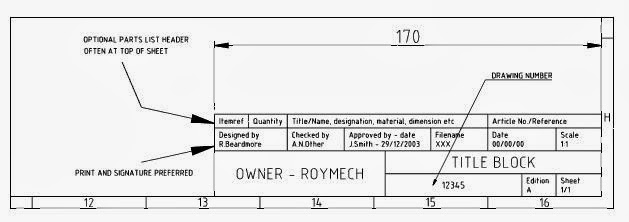
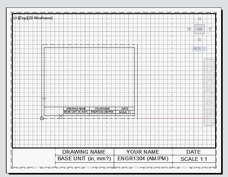
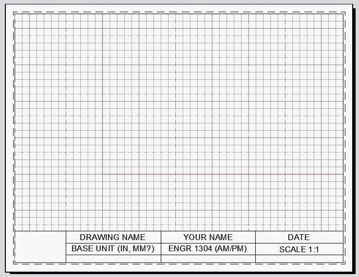
It is the frame that surrounds the plan, and a block for text in the lower right hand corner which contains information such as the author's name, date, project title, company name, part name, part number, scale, dimensioning units, material part is made out of, revisions, surface texture: welds: general tolerances and geometric tolerances, room for signatures etc.
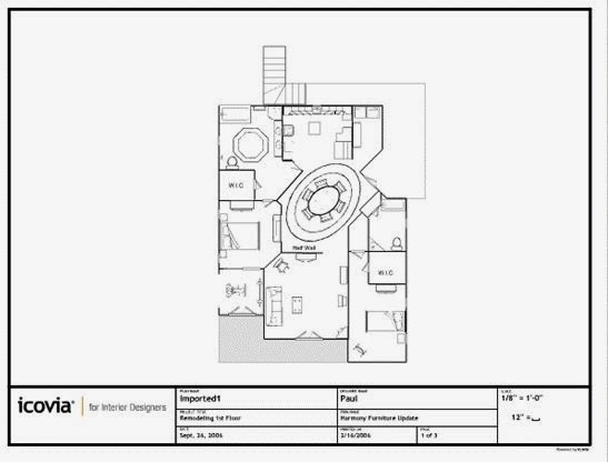
example:
Most companies have a title block format they will have you use for all of your drawings. For this class, we will create our own titleblock & frame to use for the rest of the assignments:
Draw a rectangle:
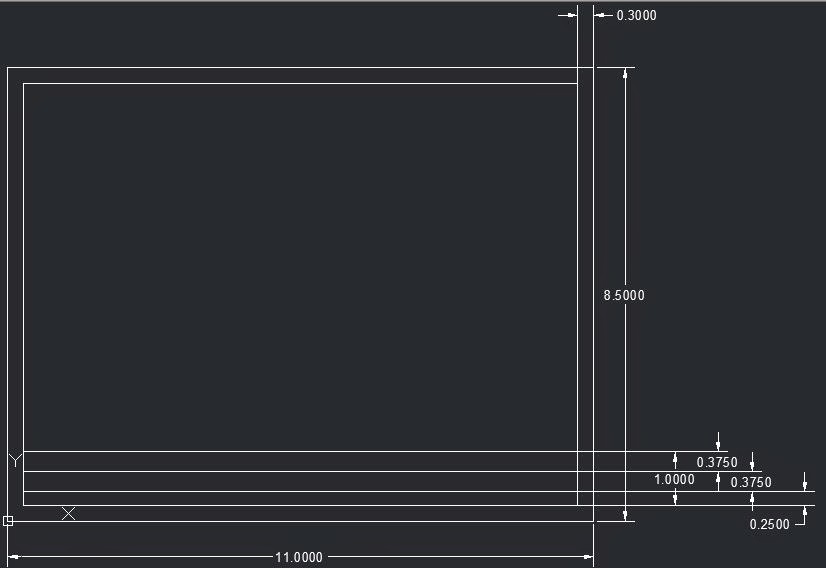
RECTANG (0,0), (11,8.5)
for an 8.5 by 11 piece of paper
OFFSET
offset rectangle by .3 - this is ~ the area the printer can use.
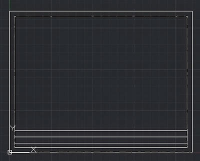
EXPLODE inner rectangle
OFFSET bottom line to build title block
OFFSET bottom line up 1.0 inch
OFFSET new line down .375 inches
OFFSET new line down .375 inches again
(leaves ~1/4 inch at the bottom)
(Do not add dimensions, dimensions are only added here to help you construct it)
Draw vertical line from the midpoint of the top line (use your object snap to find midpoint)
OFFSET vertical line 3" on each side
TRIM center lines in lower left hand corner
MTEXT: Multiline Text
TYPE "MTEXT
select only the first corner - before you select the second corner

JUSTIFY - MC - middle center
HEIGHT - 0.1875
then, after you have the text style set, select the opposite corner.
Write everything in capital letters (turn cap lock on)
COPY the text box to the other 5 regions (re size the last two to fit)
Double click on the text to edit.
Save - titleblock1
Choose Layout 1
Select everything with Ctr+a, or with a box
Right mouse click - clipboard - copy with base point, choose lower left hand corner as the base point.
Paper space vs. model space
Paper space - This is your "Print Preview" area to format your work to print on a variety of different sizes of pages.
Model space - this is where you draw your objects.
Let's format your work for printing -
Go to a layout 2 (see tabs at lower left hand corner)
Make sure you are in "paper space"
Right click on the layout tab, and make sure you are on an 8.5 by 11 piece of paper with landscape orientation.
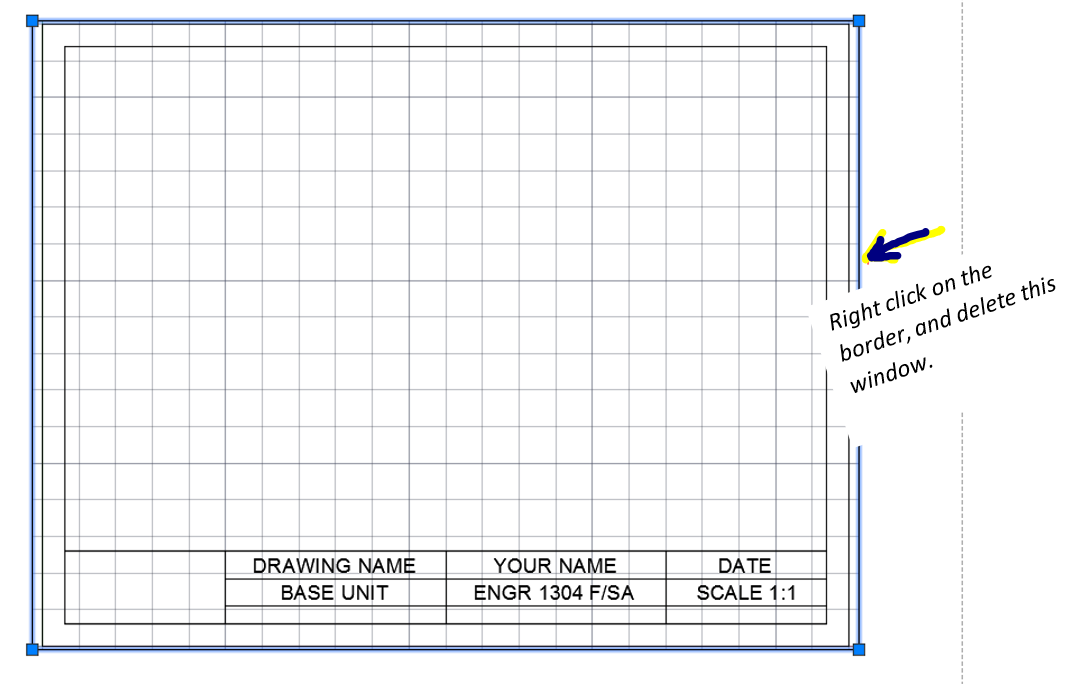
Erase the model space viewport (we'll add this back in later)
Right click, paste your title block onto the page - center it!
It should not need much modification if your page size is set up to 8.5 by 11 (Layout #2 default),
Type "VIEWPORT" into the command line, choose "single", this is how you get a window back into model space.
Copy and paste your title block in Layout #1 -
This is an 11 by 17 piece of paper, so you will need to resize the printable area, just select it, grab a blue corner and "STRETCH" it.
(if it is right next to the dashed line, chances are the border won't print, so make sure it is slightly inside the dashed lines
In the layout, in paper space, resize your view port window to fill up your drawing area.
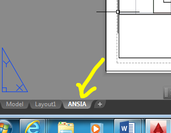
Rename your layout "ANSIA", for "A" sized piece of paper (which is 8.5 by 11). Just double click on the tab to rename it.
Make another Layout for an 11 by 17 "B" sized paper:
Go to Layout 1 (or create a new layout by right clicking on the model tab, and selecting "new layout")
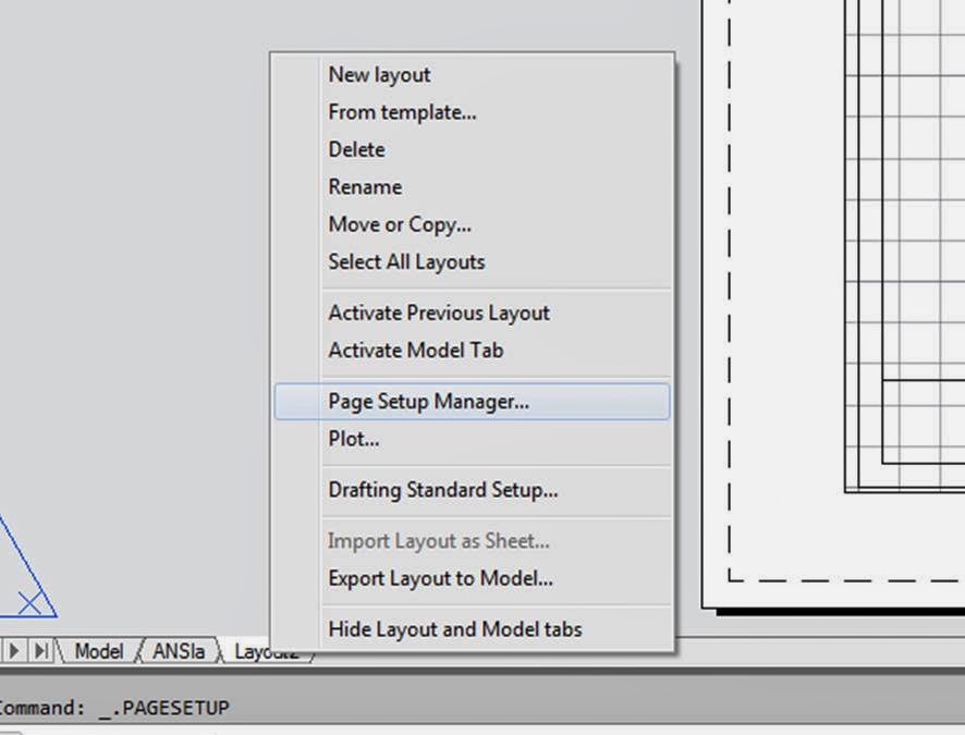
right mouse click on Layout 2, select "page setup manager"
Choose "Modify"
Under "Paper size" choose ANSI B (11.00 x 17.00 inches)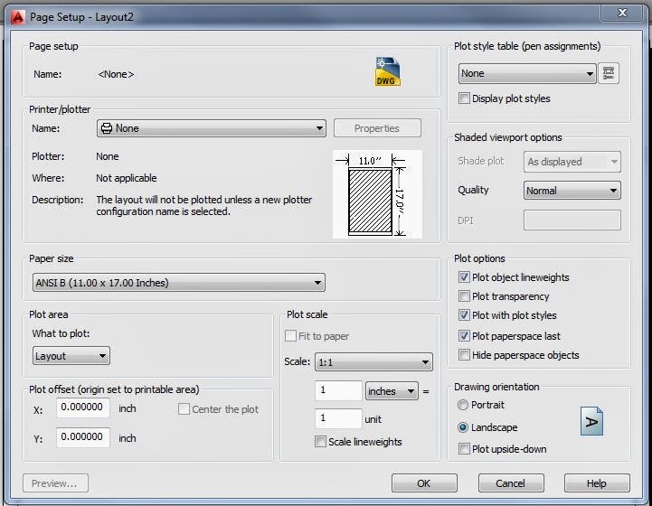
Click "ok"
then "close"
Rename Layout 1 - to ANSI B.
Erase everything in ANSI B - in paper space, (Ctrl + a - select all, delete) - this gets rid of the viewport window.
Copy everything from the ANSI A, title blcok + viewport window - (Ctrl + a, right click, copy) onto ANSI B
(Type "REGEN" to regenerate it if your copy-n-paste does not come all the way through.)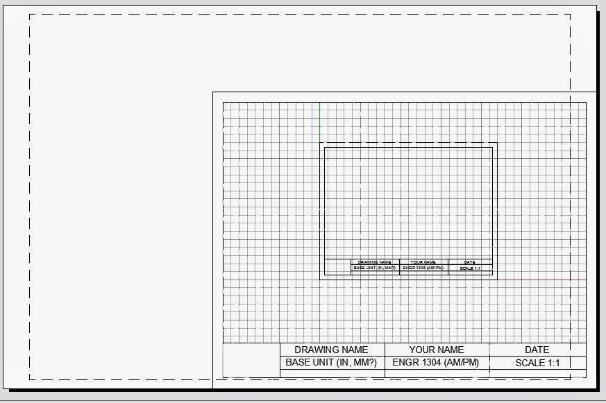
In paper space, "STRETCH" your title block and viewport out to fill in the new paper size.
1st - STRETCH it taller (Straight up)
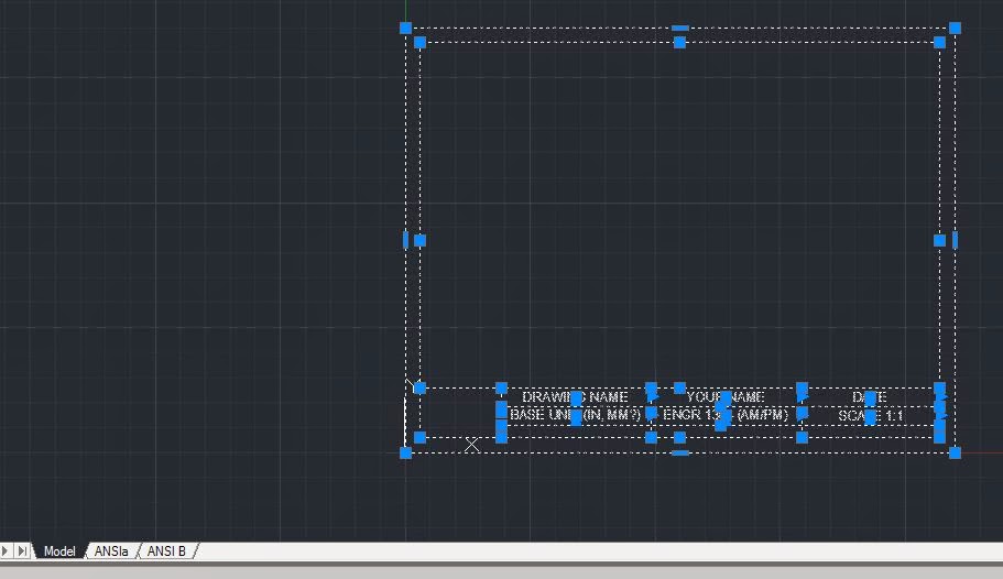
type "STRETCH"
draw a box from right to left to select top two lines
right mouse click, or click "enter"
STRETCH Specify base point or [Displacement]<displacement>: - click the upper left hand corner to Specify a base point.
Put your orthogonal snap on (bottom of the screen), and drag it straight up. (As long as it is straight up, or straight over, it will not distort the shape - where you cut it with your selection box, is what lines are going to be stretched)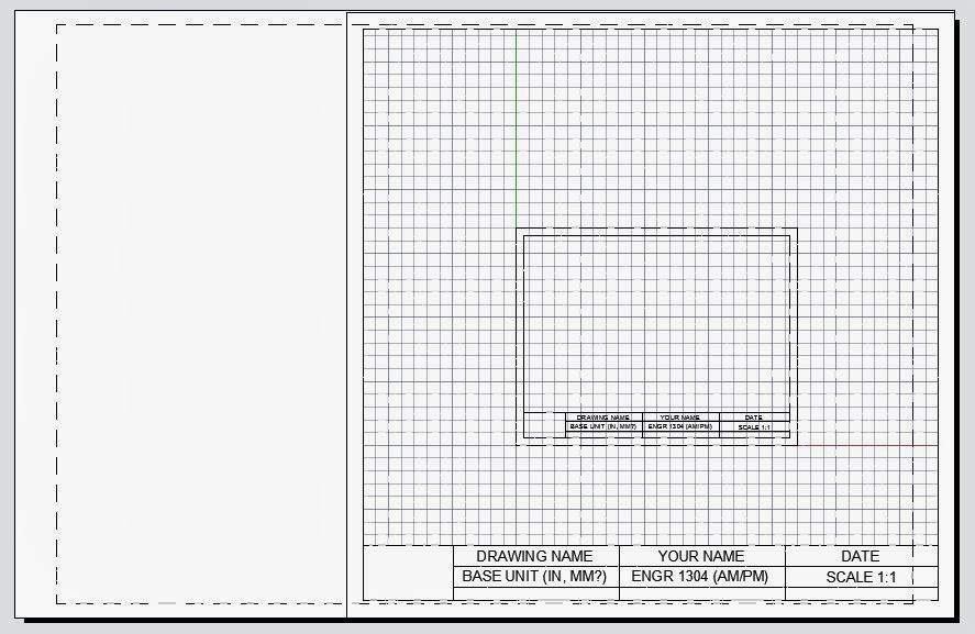
Esc Esc - then start the stretch command again, this time, select the left hand side of your box.
right mouse click (or enter)
STRETCH Specify base point of [Displacement} <Displacement>: Click on the lower left hand corner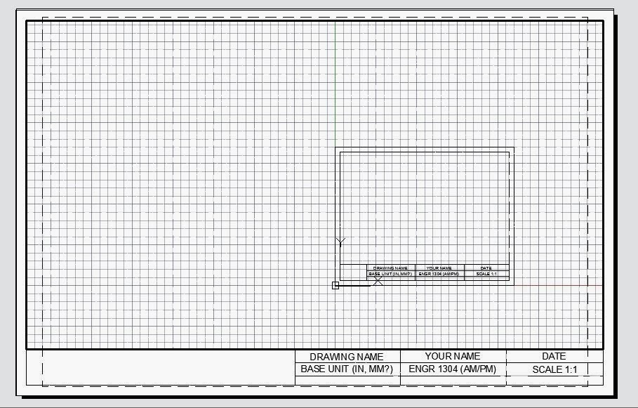
Continue to move, and stretch it, until it fits inside the printable area. Don't resize the text - move the text box within the printable space, and resize the margins!
 Rename Layer 2 - ANSI B.
From the big red "A"
Rename Layer 2 - ANSI B.
From the big red "A"
Save as a drawing - .dwg
Go into your model tab, and delete the template out of your model space. (Ctrl+a, delete)
 Now, all you have is an empty drawing area, with title blocks copied into your layouts.
 Set your snap, grid, layers (create a bunch of layers for view, hidden, construction, dimension, center, etc. with line colors chosen), and other preferences, and then
Save as a drawing template mytemplate.dwt
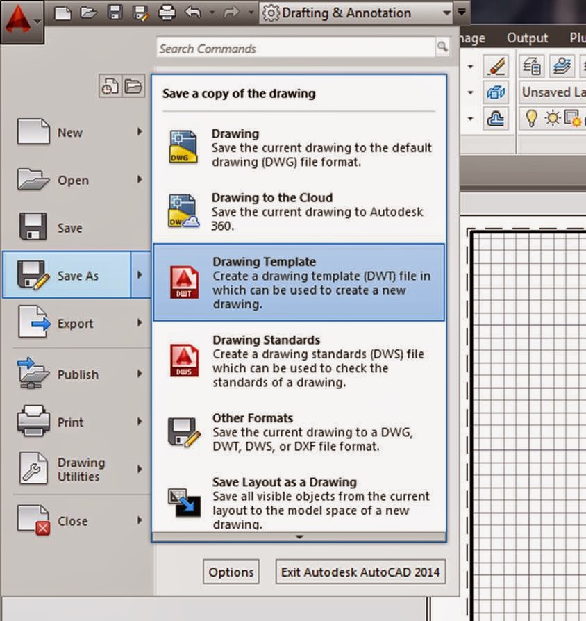 Instead of saving it in your templates folder, save it to your own personal drive.
Test is out, open up a new drawing, look through your templates, and select the one you just created.
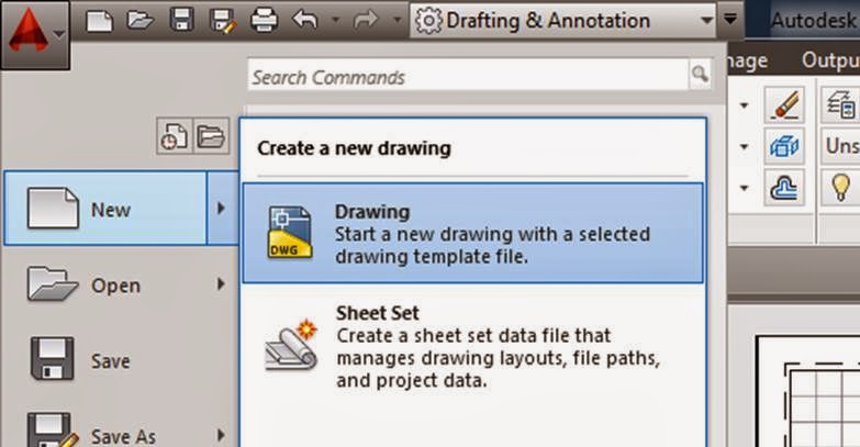
Now you don't have to recreate all your layers, settings, title blocks, etc. etc. every time you start a new drawing, just open up your template, and begin!
From now on, all of your work should be formatted on a Layout with a Title block etc. on it.
Be sure to save your template on your own personal drive (or email it to yourself) as whatever you save on the computer will be gone when the computer is turned off.


