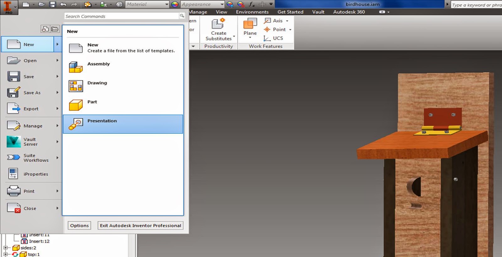
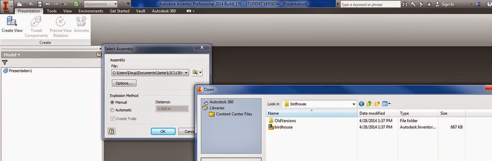
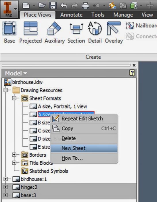
Pages

New2017 Inventor Presentation

New→Presentation


Options → just leave as default


Make sure your browser is selected under view→User interface


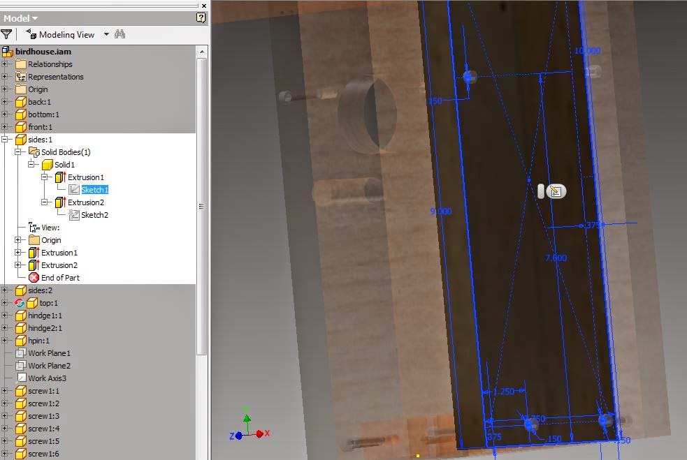
Expand the parts in your browser,
right click to turn the visibility on and off 


Right click on the corner of your ViewCube to change to perspective / Ortho views


Position your assembly with a nice orientation
Click on New Snapshot View
Right click on view to rename, make a jpg, etc.

Pull the slider on the storyboard to some time (4 seconds) to start creating a movie


Tweak components→click on a gear or other piece of your assembly→pull it away
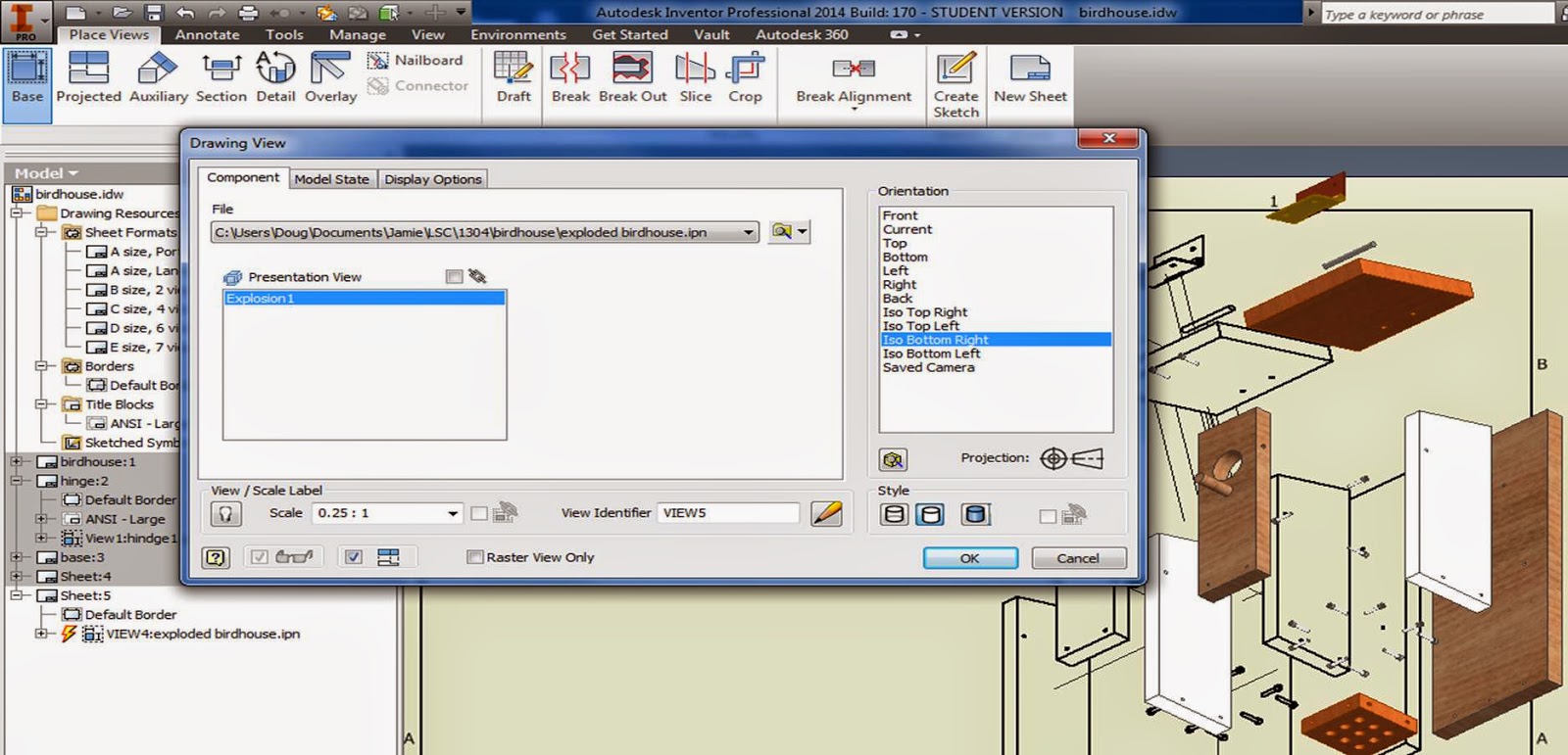
We'll explode all of the parts from one another to show the individual components and the assembly


Set the time that each motion will take, decide if you want a trail or not,

move a few of your components around

Click "OK", 


Play your movie so far!
Drag the slider to watch the motion of the components

Pull the lower menu edge to expand
Expand tweaks in the model tree
right click to edit tweaks
drag tweaks in storyboard to change timing

Click on your engine block, and try out the Opacity tool!


Try out capture camera - 

rotate assembly to a new view
click on capture camera
adjust timing in the story board


Once you have all of your components pulled apart and your video how you want it, click on the video tool, and save your movie!


Once you are finished with your movie - work on your project!
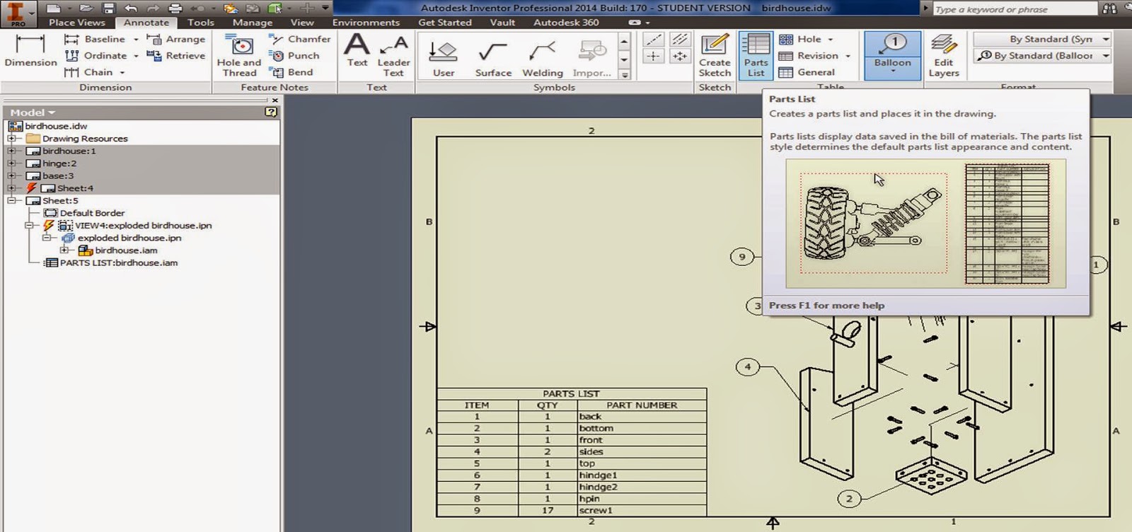
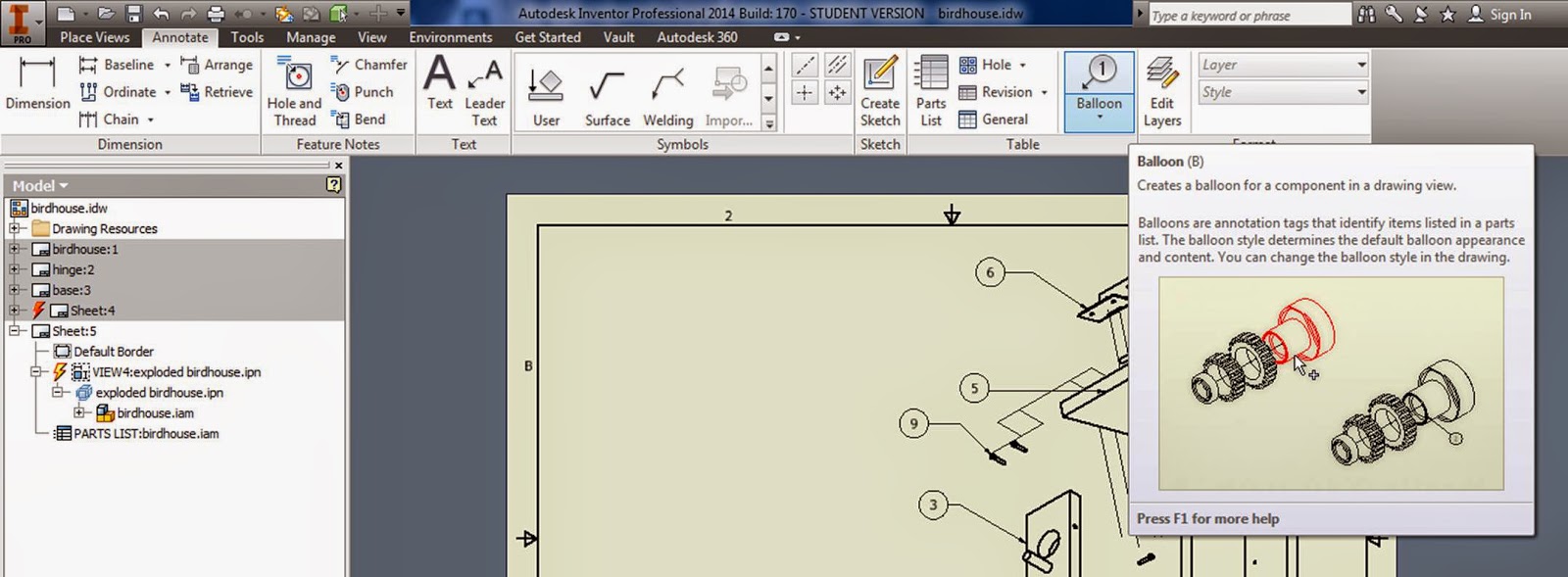
Next class - creating a set of working drawings with dimensions, parts lists, etc.


additional notes:
https://designandmotion.net/autodesk/inventor/inventor-2017-presentations/


More working drawing examples

More examples of working drawings:

3 major components of working drawings:
1. Drawing that shows how parts are assembled
2.Orthographic views of all the parts
3. Notes for all the standard parts

Assembly Drawings:
First(or last) page in a set of working drawings
Used to show how all the parts fit together.
Pictorial format - isometric, or perspective
Oriented to best show geometry of parts
Route lines - lines connecting components to one another
No hidden lines, centerlines, or dimensions
Part number balloon - circle with number that identifies part
Keep Part numbers consistent through drawing
Table with parts list - corresponding to part numbers.

Typical parts list:
Part number
Part name
Material Used
Required Quantity

Collapsed (parts assembled together)
Exploded (the assembly pulled apart)


Create pg 350, 351, 352


To insert a table, just type "TABLE", then fill in the cells like you would in excel.


For the Balloons with leader lines, type in "TP" for Tool Pallet.
Annotation - tag.
Check out all of the other tools in the tool pallet while you are there!
To rescale the size, or change anything, just select it, right click, and go to the properties box.


Detail Drawings
Orthogonal views

Dimensions for manufacturing
Part name tag
Part number balloon tag


Just use your normal dimensioning tools, then go back and double click on the dim to add more info.

%%c makes the diameter symbol


 Part Notes:


Vendor items
no orthographic views, just need a note with part info

Construction notes if needed
Outline how to assemble parts, what types of glues and materials to use, etc.


~~~~~~~~~~~~~~~~~~~~~~~~~~~~~~~~~~~~~

CAD / Inventor Assembly 
Make a complete set of working drawings for a simple assembly in either Inventor or AutoCAD.  Your set of working drawings should have:


a) An exploded assembly drawing with a parts list, balloons with leader lines.  

b) Individual parts with dimensions and tolerances labeled.


Make a birdhouse similar to the one on pg 343-346
Note: Just "similar", it doesn't have to be exact - change it to use the same size screws through the entire project so you don't have to worry about different hole sizes etc.


(I made everything out of different types of wood etc. so you could more easily see the different parts)


Example hinge:


Pages out of book:


To do this in Inventor:
Use "Project Geometry" to line up the holes for the screws.


Put all of your parts together in an assembly, then save and close all of your parts.
Double click on one of the parts in your assembly, then open up the sketch of that part from the modeling window (double click on the sketch you want to edit)


Choose "Project Geometry" from your sketching tools, then click on the holes in other parts, and project them onto the sketching plane for the part you are working on. 

Move the hole from your sketches to line up with one another (note - you might have to turn off some of your constraints, or use the move command to do this)

Then "Finish Sketch" and "Return" to get back to where you were.
Save

Making an exploded view in Inventor:

1. Assemble all of your parts so that they are all fully constrained.

2. New → Presentation


3. Create View → open up your assembly file (click on the little folder on the right hand side of your file) → open

4. You can try to automatically explode it, but this does not always work out so well (especially when you have a lot of parts).... so select "Manual".

5. Tweak Components →Components →choose a part → Direction →click on a face and a direction, grab and pull it away, create a trail →"close" when you are done.

Note: You can select more than one component at a time, so you can move screws together etc. and you can also move in one direction, then click "x , y, or z", and move in another direction before closing.


6. Click "animate" to see your components coming exploding or coming together, then save it.

7.  Create a set of working drawings:
Set up your sheets: - link
Open up multiple sheets:

Sheet Format → Choose a size →right click, New Sheet


Create all of the diagrams that you need to,

8. Create a Parts list, Balloons, and a PDF etc. for your exploded view:

In your new blank sheet:
Base view → File (click the magnifying glass, and find your ipn exploded view → change the scale, change the view orientation.


Create a Parts list:
Annotate → Parts List

Click your parts list onto the page.
Right click on it to→ "edit parts list" and change what columns and info it shows:
The upper left hand icon lets you add or remove properties to your parts list:


Then add your bubble part numbers:
It will automatically insert the correct number when you click on a part.


Youtubes going through working drawings in Inventor:
https://www.youtube.com/watch?v=XO2lE9zmhRU

https://www.youtube.com/watch?v=NBQXzL2tOGQ#t=39


Dynamic FEA

Time to test out those parts!


Create an assembly with just your connecting rod:


Remember how to use FEA?

Environments →Stress Analysis →


Create Simulation → Static Analysis


Choose a material:
6061- commonly used in machine shops

http://www.azom.com/article.aspx?ArticleID=310


Let's pretend that the timing is off, and the piston is pushing down before the Crank is able to move → add a fixed constraint to the rod cap:


What force should we apply at the top?


Is this a reasonable value?

Add mesh

 Tighten up the mesh in areas you need more accurate results or areas you think might become problematic: 0.05in?
 Right click and update the local mesh

Run the simulation!

Careful - if your mesh is too fine, this might take some time... 

Use probes to find max and min stress and strain areas - check your safety factor, and decide if you need to redesign!


Use your snipping tool to save some screen shots

Want to do a before / after modifications comparison?  Save your simulation - right click → Copy Simulation

right click on your part, open it up, modify it.

Open up the part, 
find the sketch you need, change it, then save it


Go back into your assembly
Right click on anything with a lightning bolt to update
update the mesh etc.
Compare results between simulation #1 and simulation #2.

lowest safety factor has gone from 1.5→3.  Success!