AutoCAD Intro:

tip: open this up in YouTube, adjust the speed to 1.5, and expand to watch with a full screen!
Computer Aided Drafting
Computer Aided Design
(CAM - computer aided manufacturing)
December 1982 - 1st AutoCAD released, one of the longest-lived programs.
AutoCAD's *.dwg file format standard for most CAD software
Complex and hard to learn?
In 1995 they stopped printing AutoCAD instruction manuals because the documentation package grew to about 12 volumes, and 30 pounds.
Today - a complete set of instruction manuals would take a forklift to move if you printed it.
The good news...
- Most people use the same basic 5%, and a different 5% after that. It's just a matter of finding your 5%
Getting started:
Free AutoCAD and Inventor download for students:
http://www.autodesk.com/education/free-software/all
CAD competitions:
other fun sites:
Choose "getting started" and walk through resources

Open up the program, and explore learning resources

**everyone has a different background, and will go through this stuff at different speeds.
After exploring learning resources, switch to "create" and start drawing!


→ click on the arrow under "Start Drawing"
→Choose a file format that matches the units you will use.
acad.dwt - English template
acadiso.dwt - metric drawing template
hold your cursor over a file type, and eventually a window will pop up with a description of the type of file it will create.
drawing template file ***.dwt- specify settings for text, dimensions, linetypes, etc.
drawing file ***.dwg
older versions of AutoCAD can't open newer .dwg files
new versions of CAD can always open older files
Use the "save as" option to save to older formats if needed
backup files ***.bak will be automatically saved each time you save your dwg. If you ever need a backup, rename the *.bak to *.dwg to recover previously saved drawing.
AutoCAD's default opening window:
(Type "Ribbon" into the command line if this screen does not pop up.
Hit "Cntr + 9" if there is no command line at the bottom of the screen)
 Hold your cursor over anything, and a description of the icon will pop up.
Example:

There are two ways to tell AutoCAD what to do:
1. Click on the tools in the ribbons:

2. Typing in the command line:

"What and How"
The command line at the bottom of the screen will become your best friend. When in doubt - just read the command line!!! The command line is where you tell AutoCAD "What" you want to do, and "How" you want to do it.
Example:
What: polygon (type "POLYGON" into command line)
How: how many sides do you want your polygon to have? How large do you want it? Where do you want the center?


Read the command line, and enter what it asks for.
The basic commands:
https://help.autodesk.com/view/ACD/2021/ENU/?guid=GUID-2AA12FC5-FBB2-4ABE-9024-90D41FEB1AC3
Aliases - many CAD commands have aliases - shortcut versions with fewer letters than their full commands that make it faster to type it into the command line.
L - Line
C - Close
Z A - Zoom All
U - Undo
Create a list of aliases: highlight the ones you use most often.
http://en1304.blogspot.com/2015/08/alias.html
The above list of aliases will become a dictionary of commands you can use in the command line.
To start a command, type it's UPPER CASE letter:
command: LINE
alias: L

UNITS: command to set the unit type
- You decide what the length of one unit represents—an inch, a foot, a centimeter, a kilometer, etc. You should decide what units you need before you start drawing anything.
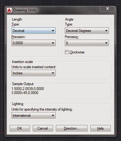
- Note: changing the unit format and precision does not affect the internal precision of your drawing. It affects only how lengths, angles, and coordinates are displayed in the user interface
imperial (i) assume your units are inches, set unit type to Architectural, use acad.dwt or acadlt.dwt.
metric (m) assume your units are millimeters, leave the unit type set to Decimal, use acadiso.dwt or acadltiso.dwt templates.
If you change the UNITS settings, make sure that you save the drawing as a drawing template file. Otherwise, you will need to change the UNITS settings for each new drawing.
Length Units:
Architectural - units based in feet and inches and use fractions to represent partial inches. The base unit is one inch.
Decimal - units are unitless, that is, they're not based on any particular real-world unit.
Engineering - units are based in feet and inches and use decimals to represent partial inches, for example 12'3.5"
Fractional units, like decimals units, are unitless and show values as fractions rather than decimal numbers: 15 1/2
Scientific units, also unitless and show values as exponents, are used for drawing really tiny or really large.
Angle Units:
Decimal Degrees: Show angles as decimal numbers, easiest to work with.
Deg/min/sec - old style of dividing a degree into minutes and seconds.
Grads and Radians - not widely used in drafting
Surveyor's Units - similar to Deg/Min/Sec but uses quadrants (quarter circles) rather than a whole circle.

Mouse:
Left click - select objects
rectangular selection - click one corner, then click other corner
Lasso - hold left button down
left→right selects everything completely within your box or loop
right→left selects anything you touch.
Right click in the command line or on anything for options/properties
Wheel:
- Zoom in or out by rolling the wheel.
- Pan a view in any direction by holding the wheel down and then moving your mouse.
- Zoom to the extents of your model by clicking the wheel twice.
-Shift+click on wheel and move mouse - rotate object

~~~~~~~~~~~~~~~~~~~~~~~~~~~~~~~~~~~~~~~~
Model vs. Paper space:
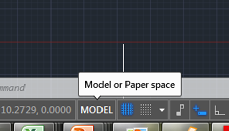
Model - Where you create and modify objects that represent things in the real world. Create your models at full size (1:1 scale).
Paper - Where you create particular views of object for plotting, usually with a title block. Scale drawing to fit onto the piece of paper you are printing it onto. Paper space has one or more layouts, each layout has a different arrangement of model space views and different title block information.** Make sure you are in model space when you are drawing!!!
~~~~~~~~~~~~~~~~~~~~~~~~~~~~~~~~~~~~~~~~~~~~~~~~~~~~~~~~~~~~~~~~~~~~~~~
OK - let's start drawing!
Hit "Esc" a couple of times to clear out any previous commands.
Note: You will be hitting Esc over and over again in CAD. If it is not doing what you want it to, it's probably jammed up with previous commands that have not been turned off. Hit Esc a few times, and then retry what you were doing.
Type the words in bold into the command line at the bottom of your screen.
1. Set up an appropriate size for the drawing:
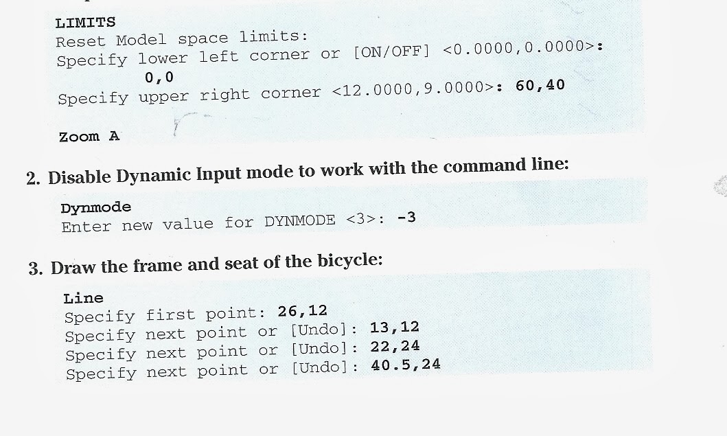


AutoCAD is not drawing a picture, it is creating a graph. You can zoom in and this image will never become pixilated because it is not an image, it is a set of data.
Let's explore a few more drawing tools.
Offset - creates a new entity parallel to the original
Offset
Specify offset distance or [Through Erase Layer] <Through>:
if you hit "Enter" whatever is <inside these brackets> will be selected. Type in "0.5" for the offset distance.
Select object to offset or [Exit Undo] <exit>
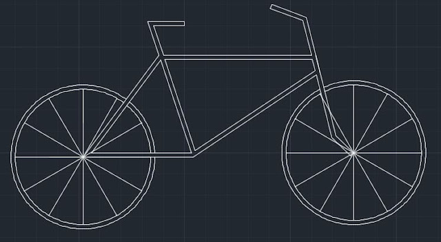
Use your cursor to select the tires on your bike
Specify point on side to offset or [Exit / Multiple / Undo] <exit>:
Click anywhere outside the circle to create a second circle.

Practice using the offset command around the frame of your bike.

Notice that you have to select each line individually, and that the offset command has left the intersections between lines messy.
Try out some editing tools.

Trim - removes parts of objects by using others as cutting edges
Zoom in on a section in your bike by rolling the wheel on your mouse.
Type "Trim" into your command line, or select it from the modify tools in your ribbon:

If you hold your cursor over a tool in the ribbon, eventually a description of the tools with instructions on how to use it will pop up.
Using trim takes 3 clicks - 2 clicks to select your cutting planes (after which you hit enter) and then one click on each of the lines between your cutting planes that you want to remove.
Shift + click will undo a selection if you accidentally click on a line you did not want to.
Practice using trim for a few of the overlapping lines on your bike frame.

Note: the easiest way to trim is to just "select all" for your cutting edges.
Select objects or <select all>: (hit enter to select all)
After <select all> you can trim anything you want without having to go back and continually change your cutting edges.
Some additional trim commands:
Extrim: link


To trim the spokes, you will first need to "Explode" them. Right now they are all connected into one object. Before you trim them, you need to split them up into individual lines. Just type "Explode" and select the spokes, then trim the spokes so that the frame is on top.

Now, let's fill in the frame with "Hatch"

Click on "settings" in the command line, then choose your hatch pattern, color, etc.

Use a different hatch pattern for your tires.

Save your bike, submit it to course activities→assignments→2D AutoCAD intro.


(Type "Ribbon" into the command line if this screen does not pop up.
Hit "Cntr + 9" if there is no command line at the bottom of the screen)
Example:

There are two ways to tell AutoCAD what to do:
1. Click on the tools in the ribbons:
2. Typing in the command line:

Clicking tools in the ribbon will also fill text into command line.
The command line at the bottom of the screen will become your best friend. When in doubt - just read the command line!!! The command line is where you tell AutoCAD "What" you want to do, and "How" you want to do it.
Example:
What: polygon (type "POLYGON" into command line)
How: how many sides do you want your polygon to have? How large do you want it? Where do you want the center?
Default options are listed first with [additional ways to draw an object in brackets] ← click on text in bracket, or type first letter to change how you want to draw it.
Read the command line, and enter what it asks for.
The basic commands:
https://help.autodesk.com/view/ACD/2021/ENU/?guid=GUID-2AA12FC5-FBB2-4ABE-9024-90D41FEB1AC3
Aliases - many CAD commands have aliases - shortcut versions with fewer letters than their full commands that make it faster to type it into the command line.
L - Line
C - Close
Z A - Zoom All
U - Undo
Create a list of aliases: highlight the ones you use most often.
http://en1304.blogspot.com/2015/08/alias.html
The above list of aliases will become a dictionary of commands you can use in the command line.
To start a command, type it's UPPER CASE letter:
command: LINE
alias: L
UNITS: command to set the unit type
- You decide what the length of one unit represents—an inch, a foot, a centimeter, a kilometer, etc. You should decide what units you need before you start drawing anything.
- Note: changing the unit format and precision does not affect the internal precision of your drawing. It affects only how lengths, angles, and coordinates are displayed in the user interface
imperial (i) assume your units are inches, set unit type to Architectural, use acad.dwt or acadlt.dwt.
metric (m) assume your units are millimeters, leave the unit type set to Decimal, use acadiso.dwt or acadltiso.dwt templates.
If you change the UNITS settings, make sure that you save the drawing as a drawing template file. Otherwise, you will need to change the UNITS settings for each new drawing.
Length Units:
Architectural - units based in feet and inches and use fractions to represent partial inches. The base unit is one inch.
Decimal - units are unitless, that is, they're not based on any particular real-world unit.
Engineering - units are based in feet and inches and use decimals to represent partial inches, for example 12'3.5"
Fractional units, like decimals units, are unitless and show values as fractions rather than decimal numbers: 15 1/2
Scientific units, also unitless and show values as exponents, are used for drawing really tiny or really large.
Angle Units:
Decimal Degrees: Show angles as decimal numbers, easiest to work with.
Deg/min/sec - old style of dividing a degree into minutes and seconds.
Grads and Radians - not widely used in drafting
Surveyor's Units - similar to Deg/Min/Sec but uses quadrants (quarter circles) rather than a whole circle.

Mouse:
Left click - select objects
rectangular selection - click one corner, then click other corner
Lasso - hold left button down
left→right selects everything completely within your box or loop
right→left selects anything you touch.
Right click in the command line or on anything for options/properties
Wheel:
- Zoom in or out by rolling the wheel.
- Pan a view in any direction by holding the wheel down and then moving your mouse.
- Zoom to the extents of your model by clicking the wheel twice.
-Shift+click on wheel and move mouse - rotate object

~~~~~~~~~~~~~~~~~~~~~~~~~~~~~~~~~~~~~~~~
Model vs. Paper space:
Model - Where you create and modify objects that represent things in the real world. Create your models at full size (1:1 scale).
Paper - Where you create particular views of object for plotting, usually with a title block. Scale drawing to fit onto the piece of paper you are printing it onto. Paper space has one or more layouts, each layout has a different arrangement of model space views and different title block information.** Make sure you are in model space when you are drawing!!!
~~~~~~~~~~~~~~~~~~~~~~~~~~~~~~~~~~~~~~~~~~~~~~~~~~~~~~~~~~~~~~~~~~~~~~~
OK - let's start drawing!
Hit "Esc" a couple of times to clear out any previous commands.
Note: You will be hitting Esc over and over again in CAD. If it is not doing what you want it to, it's probably jammed up with previous commands that have not been turned off. Hit Esc a few times, and then retry what you were doing.
Type the words in bold into the command line at the bottom of your screen.
1. Set up an appropriate size for the drawing:

AutoCAD is not drawing a picture, it is creating a graph. You can zoom in and this image will never become pixilated because it is not an image, it is a set of data.
Let's explore a few more drawing tools.
Offset - creates a new entity parallel to the original
Offset
Specify offset distance or [Through Erase Layer] <Through>:
if you hit "Enter" whatever is <inside these brackets> will be selected. Type in "0.5" for the offset distance.
Select object to offset or [Exit Undo] <exit>
Use your cursor to select the tires on your bike
Specify point on side to offset or [Exit / Multiple / Undo] <exit>:
Click anywhere outside the circle to create a second circle.

Practice using the offset command around the frame of your bike.

Notice that you have to select each line individually, and that the offset command has left the intersections between lines messy.
Try out some editing tools.

Trim - removes parts of objects by using others as cutting edges
Zoom in on a section in your bike by rolling the wheel on your mouse.
Type "Trim" into your command line, or select it from the modify tools in your ribbon:

If you hold your cursor over a tool in the ribbon, eventually a description of the tools with instructions on how to use it will pop up.
Using trim takes 3 clicks - 2 clicks to select your cutting planes (after which you hit enter) and then one click on each of the lines between your cutting planes that you want to remove.
Shift + click will undo a selection if you accidentally click on a line you did not want to.
Practice using trim for a few of the overlapping lines on your bike frame.

Note: the easiest way to trim is to just "select all" for your cutting edges.
Select objects or <select all>: (hit enter to select all)
After <select all> you can trim anything you want without having to go back and continually change your cutting edges.
Some additional trim commands:
Extrim: link
Now, let's add some spokes onto the tires!
Array - creates rectangular or polar patterns by copying something.
The center of your tires are at:
(13, 12)
(45, 12.5)
Draw a horizontal line from the center of your tire to the edge:

Command: ARRAY
Select objects: (click on line)
1 found
Select objects:Enter array type [Rectangular/PAth/POlar] <Rectangular>: PO
Type = Polar Associative = Yes
Specify center point of array or [Base point/Axis of rotation]:
click on the center of the tire
Select grip to edit array or [ASsociative/Base point/Items/Angle between/Fill angle/ROWs/Levels/ROTate items/eXit]<eXit>:

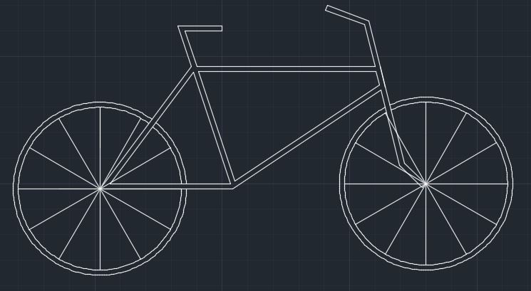
Create 12 spokes in each bike tire:

Now, let's fill in the frame with "Hatch"

Click on "settings" in the command line, then choose your hatch pattern, color, etc.

Use a different hatch pattern for your tires.

Save your bike, submit it to course activities→assignments→2D AutoCAD intro.


↑Cristhian Garcia's bike - pretty nice!!

