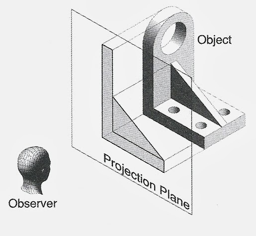
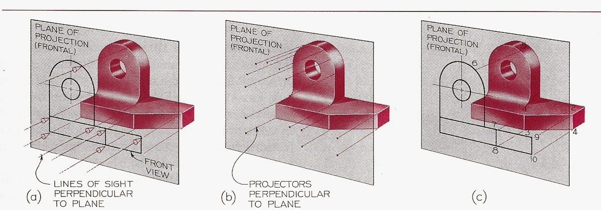
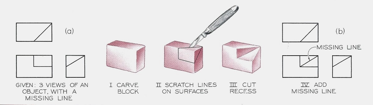
Orthographic (Multiview) projections (or orthogonal projection)
way to represent 3D objects in 2D
use parallel projection,
way to represent 3D objects in 2D
use parallel projection,
projection lines are "orthogonal" to the projection plane
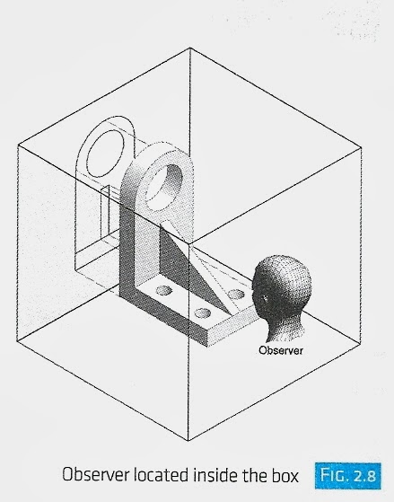
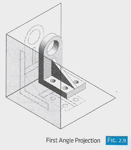
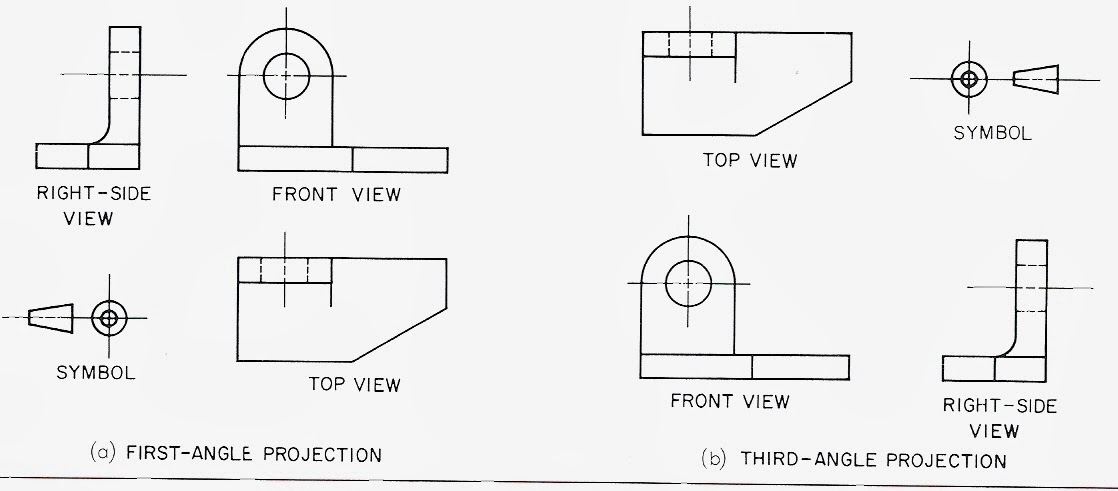
First angle projection - view object from inside the box
Third angle projection - view from outside the box:
(3rd angle projection - ASME Y14.3-2003 - US standard is 3rd angle)
First angle projection - view object from inside the box
Third angle projection - view from outside the box:
(3rd angle projection - ASME Y14.3-2003 - US standard is 3rd angle)
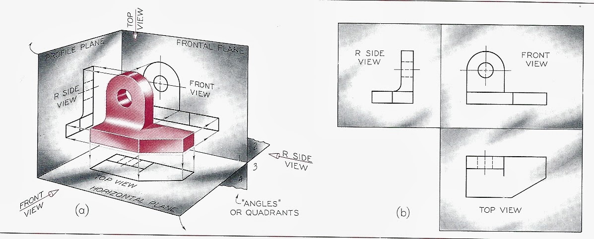
Axonometric projection
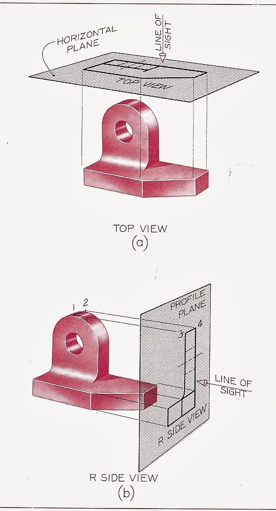
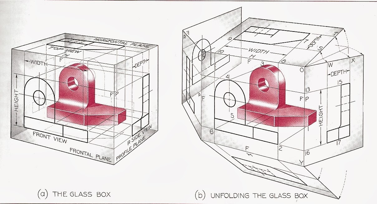
Orthographic projections which reveal more than one side of a 3D object.
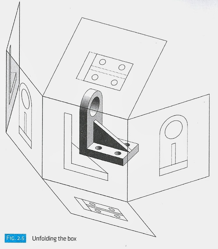
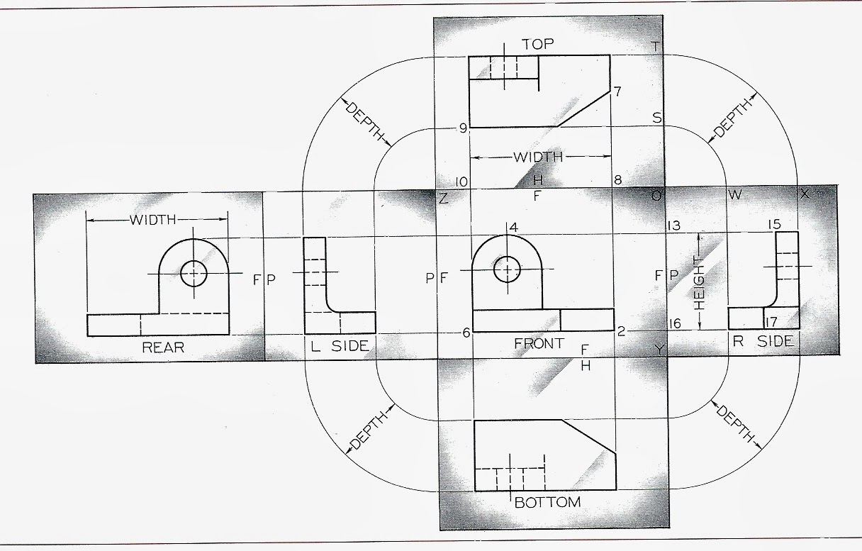
Encapsulate object in a glass box:
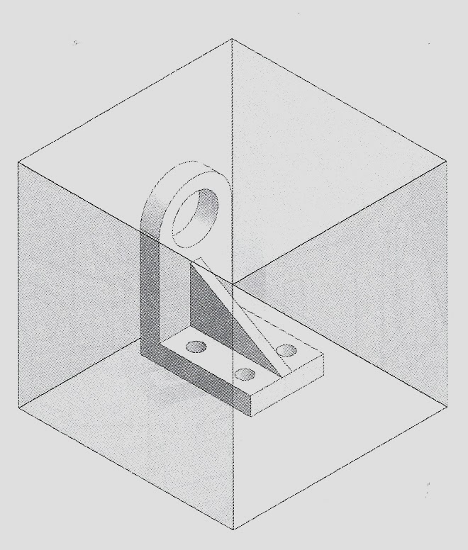
Use orthogonal projection lines to create 6 views of the object:
Orthographic projections which reveal more than one side of a 3D object.
Encapsulate object in a glass box:
Use orthogonal projection lines to create 6 views of the object:
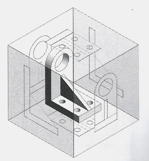
Unfold the box:
Complete orthographic View, 6 principle views.

Standard View: 3 necessary views.

First angle projection - observer inside the box
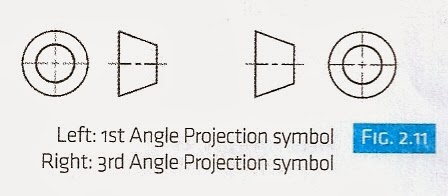
Symbols for 1st and 3rd angle projection.
Three main types of axonometric projections:
Trimetric: no equal sides or angles
Dimetric: 2 equal sides, equal angles
Isometric: 3 equal sides, equal angles
Dimetric: 2 equal sides, equal angles
Isometric: 3 equal sides, equal angles

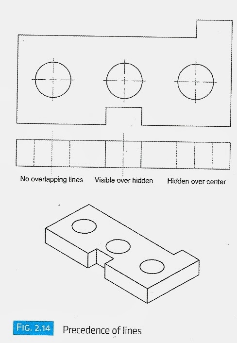
Line types:

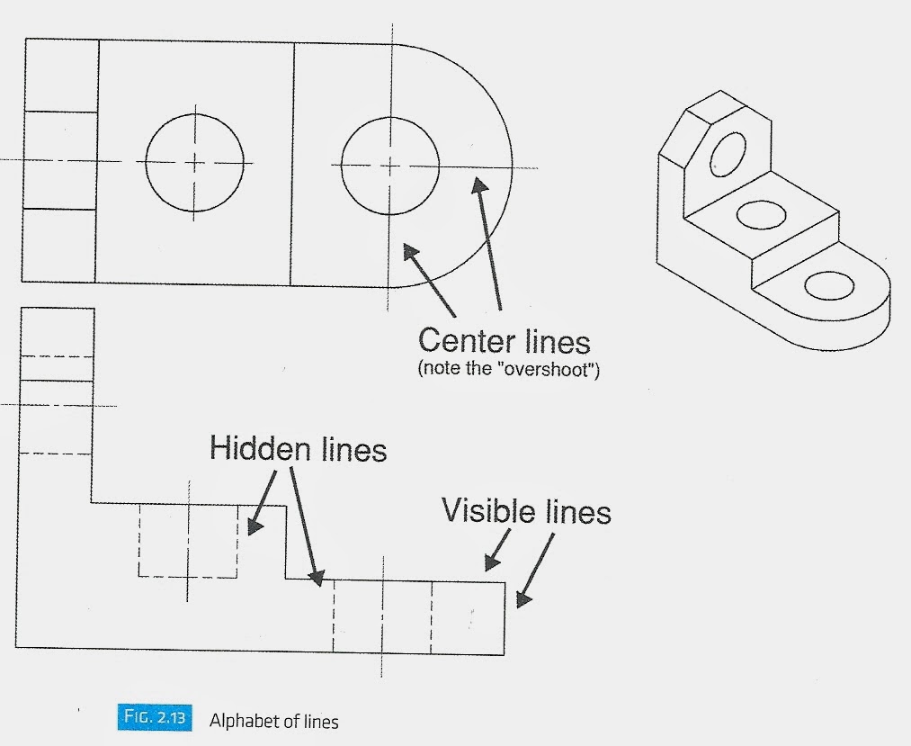
Visible lines over hidden lines
Hidden over center lines
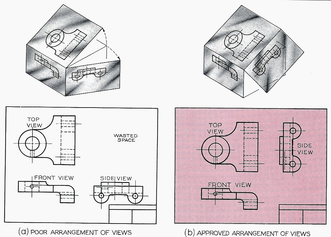
Orient views to minimize depth and conserve space.


Put the top at the top:


Select views to minimize the number of hidden lines.
If the left and right sides are the same, use the right side.
Foreshortening:
Feature appears shorter than true length due to angle it is viewed from.
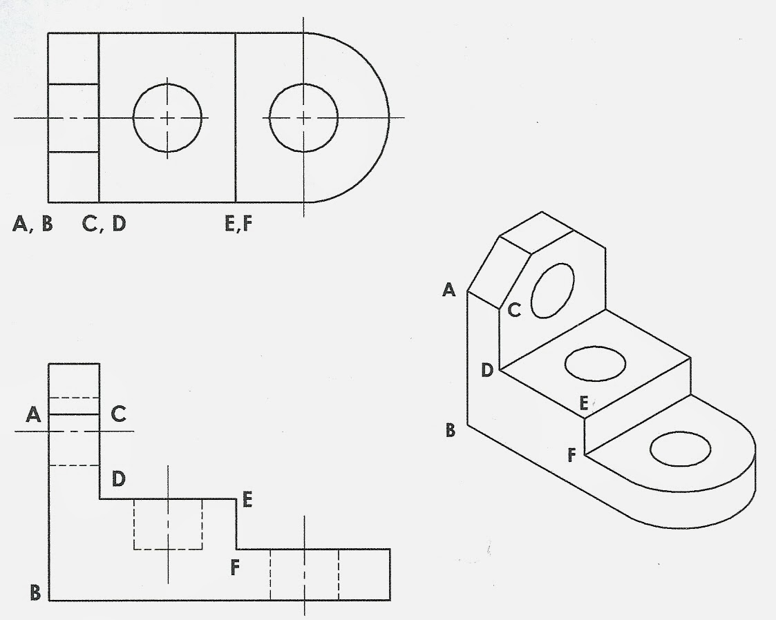
Labeling edges and points "A, B, C, D..."
corner in one view = edge in another view.
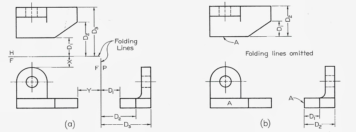
Folding Lines: hinge lines of the glass box
folding lines help you visualize the glass box.
Distances depend on object placement in box.
they are generally omitted from the final draft.
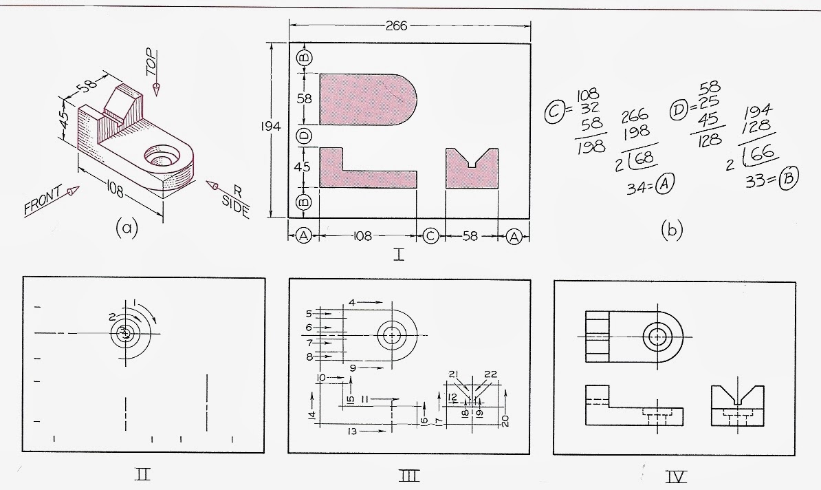
Two-View instrument drawing:
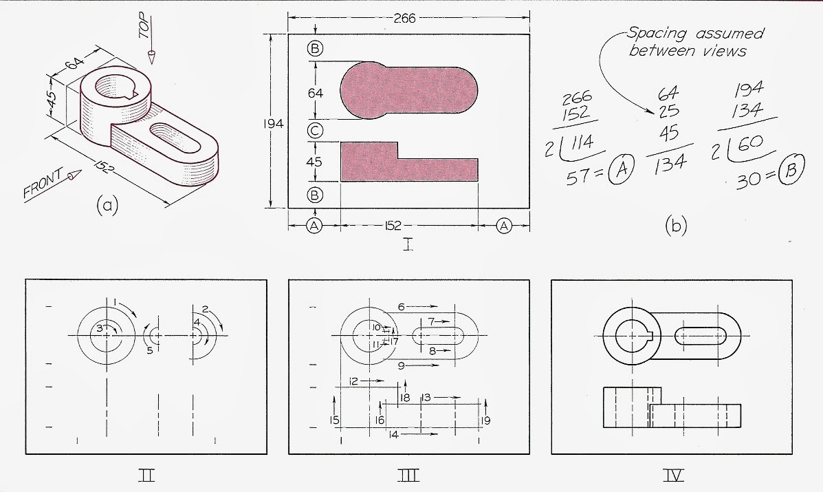
I. Determine spacing of views to center drawing on page.
II. Locate center lines from spacing marks. Lightly construct circles and arcs.
III. Draw horizontal, and then vertical construction lines. Allow construction lines to cross at corners.
IV Erase construction lines. Add hidden lines and heavy in all final lines.
Transferring Depth Dimensions:
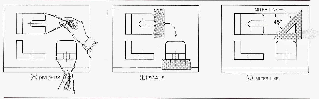
All dimensions in the top and side views must be the same.
45 miter-line method for transferring depth dimensions:
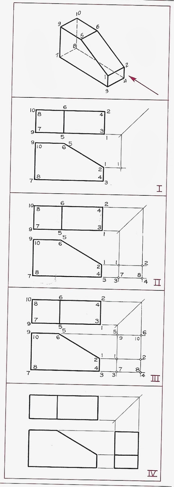
Number the corners to help connect corresponding views.
Visible points - number is placed outside the corner
Hidden points - number is placed inside the corner
Hidden points - number is placed inside the corner
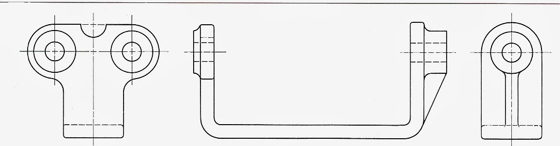
Three-View Instrumental Drawing:
I. Determine the spacing of the views.
II. Locate center lines from spacing marks.
III. Draw horizontal, then vertical, then inclined construction lines.
IV. Add hidden lines, erase construction lines, heaven in final lines.
Alternative Positions of Views:wide, flat object
II. Locate center lines from spacing marks.
III. Draw horizontal, then vertical, then inclined construction lines.
IV. Add hidden lines, erase construction lines, heaven in final lines.
Alternative Positions of Views:wide, flat object
Partial Views
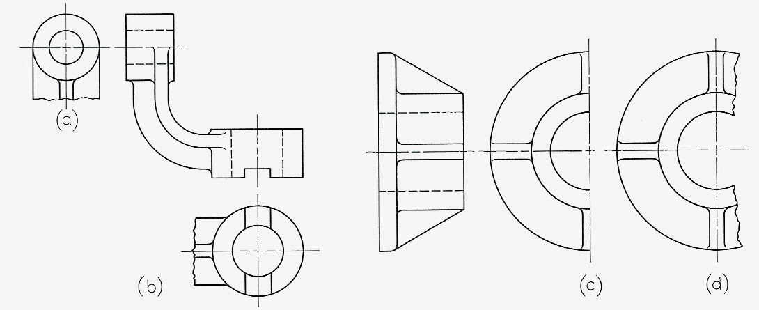
(a), (b), use break lines where the contour limits the view.
(c), (d), If it is symmetrical, half views (c), or partial view (d) can be used.
Incomplete Side View:If a complete side view, with all the hidden lines of everything on both sides is too messy, partial views showing just one side can be used.
(c), (d), If it is symmetrical, half views (c), or partial view (d) can be used.
Incomplete Side View:If a complete side view, with all the hidden lines of everything on both sides is too messy, partial views showing just one side can be used.
Revolution Conventions:
(b) regular projection is confusing due to foreshortening
(c) each feature is revolved to lie at 180 degrees from one another to make it simpler to read.
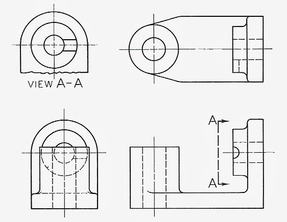
Removed View: complete or partial view removed to another place on the sheet so that it no longer is in direct projection with any other view.
A-A: viewing plane.
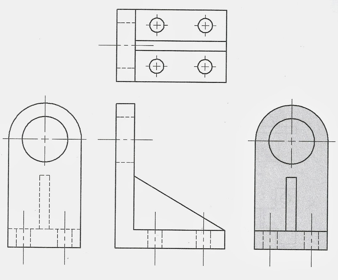
Visualizing from Given Views:
Visualization: study and visualize the 3D shape from the 2D views.
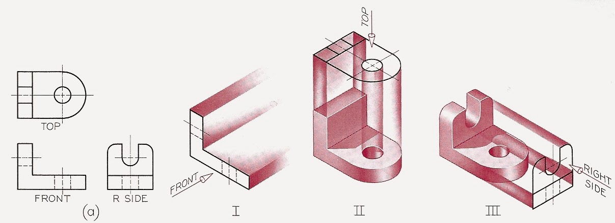
I. When you first look at the front view, the meaning of the hidden lines are not yet clear, and the curvature of the front cannot be understood.
II. Through mentally combining the front and top views, some of the hidden lines can now be understood, and the curvature of the front seen.
III. Only after combining all 3 views can the object be correctly visualized in 3D.
Use of models to aid visualization:
If you have trouble visualizing the 3D object from the 2D projections, get some modeling clay or play dough, and make the object.
soap models:
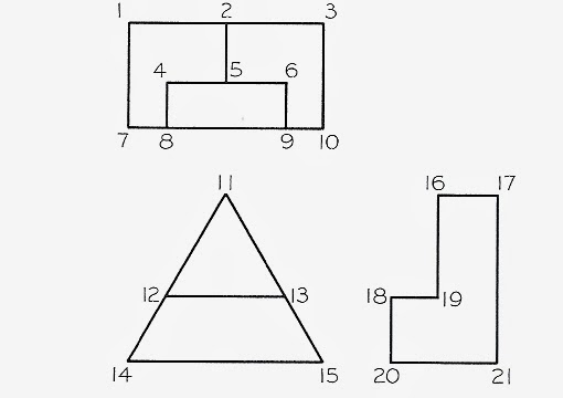
Surfaces, Edges, and Corners
surface (plane)
bounded by straight lines or curves
frontal, horizontal, or profile
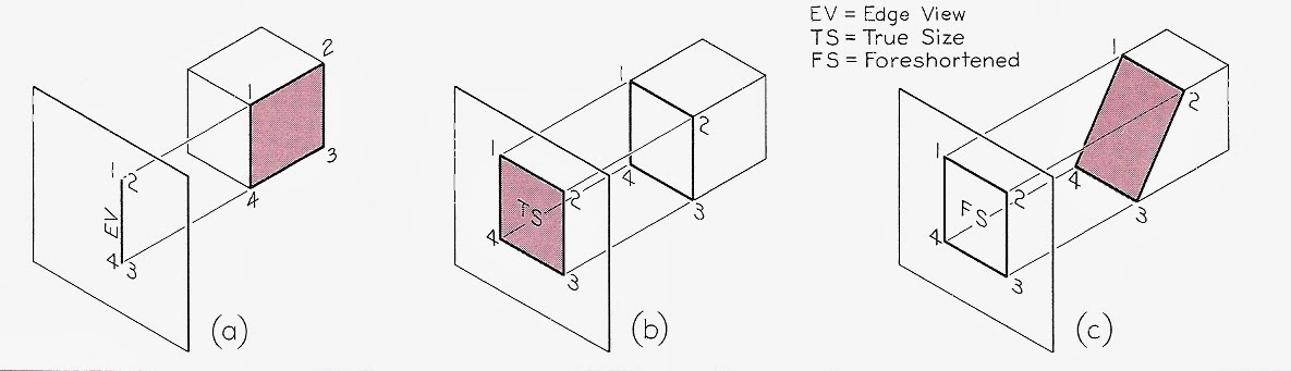
(a) EV edge view, surface appears as a line
(b) TS, true surface
(c) FS foreshortened surface
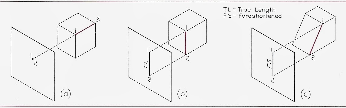
(a) point that represents edge
(b) TL = true line
(c) FS = foreshortened line.
(b) TL = true line
(c) FS = foreshortened line.
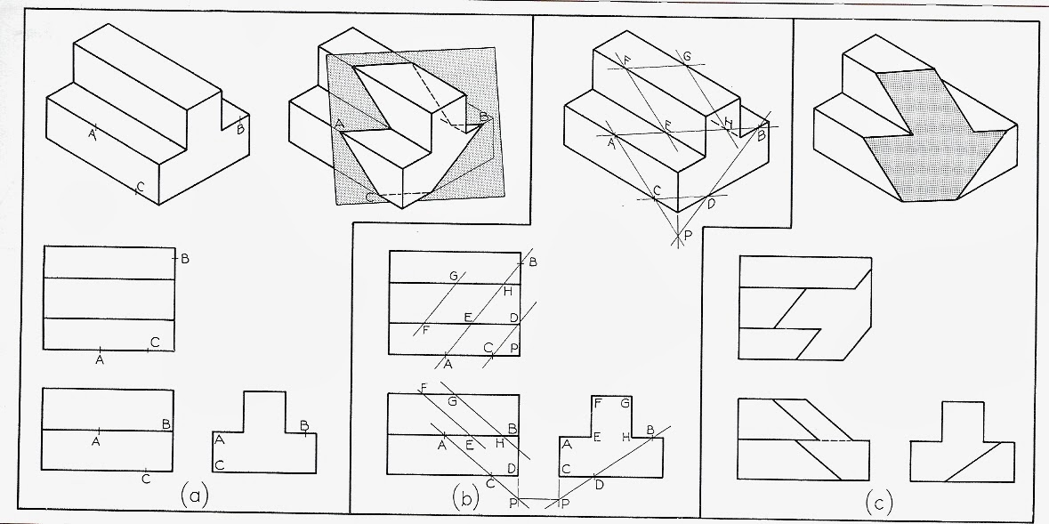
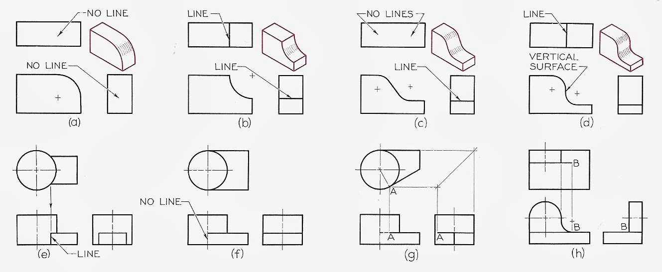
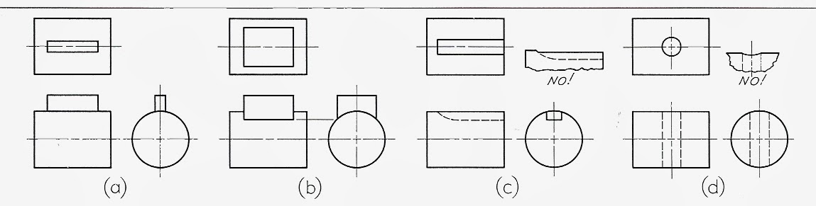
Adjacent areas
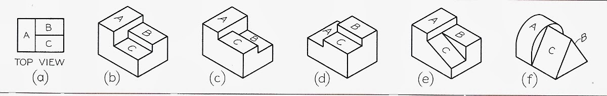
(a) top view with lines separating different surfaces
(b), (c), (d), (e), (f) different possible meanings for the top view.
note: No two adjacent areas can lie in the same plane.
Similar Shapes:
(b), (c), (d), (e), (f) different possible meanings for the top view.
note: No two adjacent areas can lie in the same plane.
Similar Shapes:
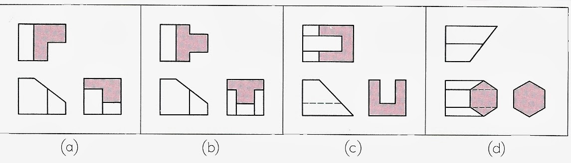
Can you visualize the above 3D objects? Try to sketch an isometric projection of each.
Reading a Drawing:No curved lines in any of the views means all surfaces are created by plane surfaces.
Reading a Drawing:No curved lines in any of the views means all surfaces are created by plane surfaces.
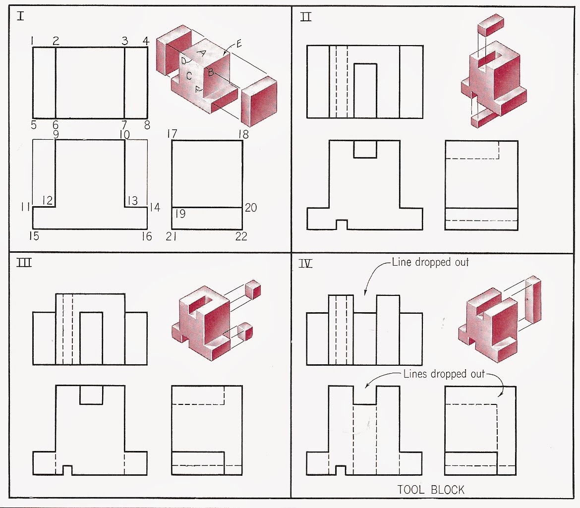
Normal Surface:
plane surface that is parallel to a plane of projection.
appears in true size and shape on the projection (no foreshortening)
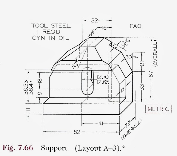
Machining a tool block - normal surfaces and edges.
plane surface that is parallel to a plane of projection.
appears in true size and shape on the projection (no foreshortening)
Machining a tool block - normal surfaces and edges.
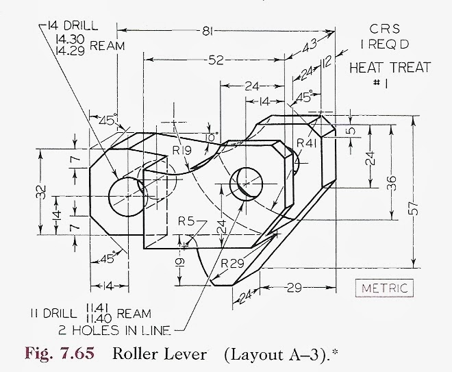
Machining a Control Lever - Inclined and Oblique Surfaces
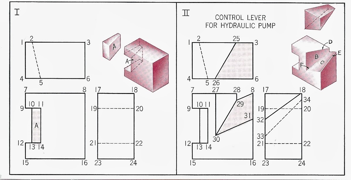
Parallel Lines
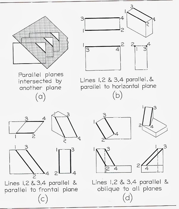
Oblique Edge - cannot appear as a point in any view, not perpendicular to any surface.
Oblique Surfaces:
Oblique surfaces - always appear foreshortened, not perpendicular to any surface.
Angles:
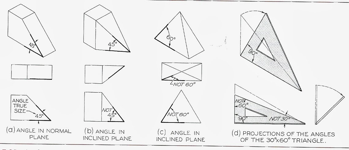
(a) If an angle is in a normal plane, that is, parallel to a plane of projection, the angle will be shown true size on the plane of the projection to which it is parallel.
(b), (c) If the angle is an inclined plane, it may be projected either larger or smaller than the true angle depending on its position.
(b) 45 is oversize in the front view
(c) 60 is undersized in both views.
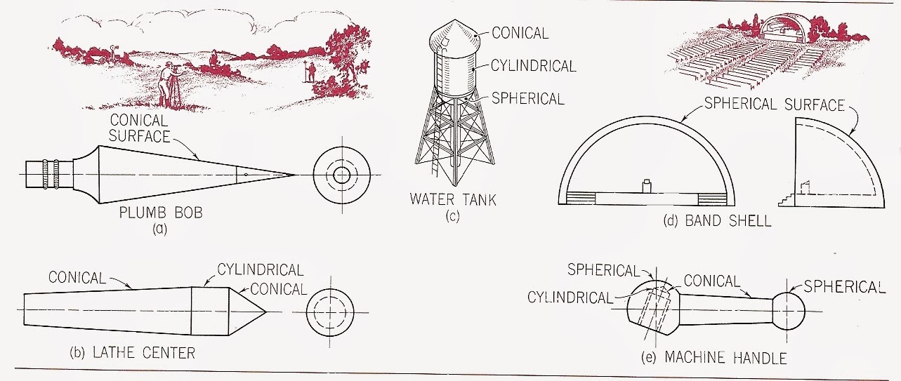
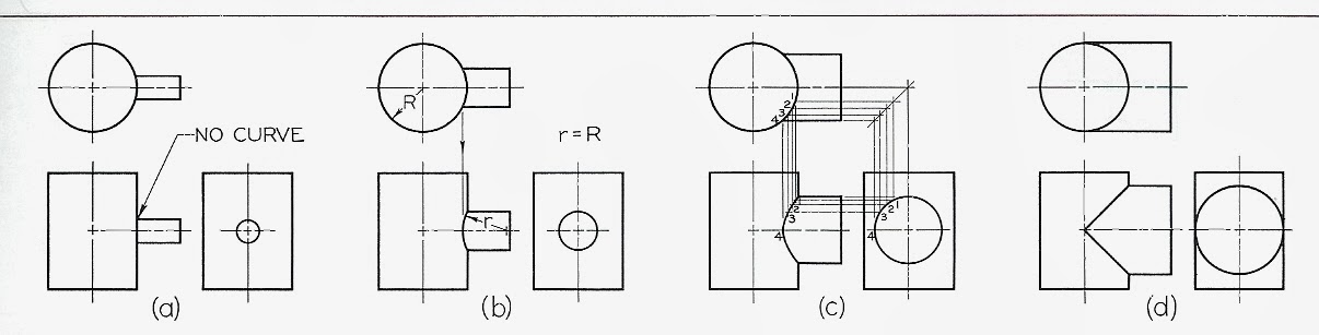
Cylindrical Surfaces
(b), (c) If the angle is an inclined plane, it may be projected either larger or smaller than the true angle depending on its position.
(b) 45 is oversize in the front view
(c) 60 is undersized in both views.
Cylindrical Surfaces
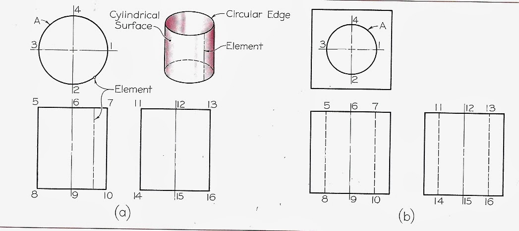
(a) Right-circular cylinder, all edges are "circular edges"
(b) cylindrical hole in a right square prism
Curved Surfaces:Rounded surfaces formed by lathe, drill press, etc. are common.
(b) cylindrical hole in a right square prism
Curved Surfaces:Rounded surfaces formed by lathe, drill press, etc. are common.
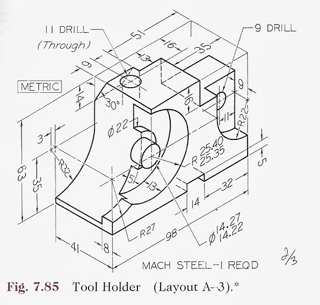
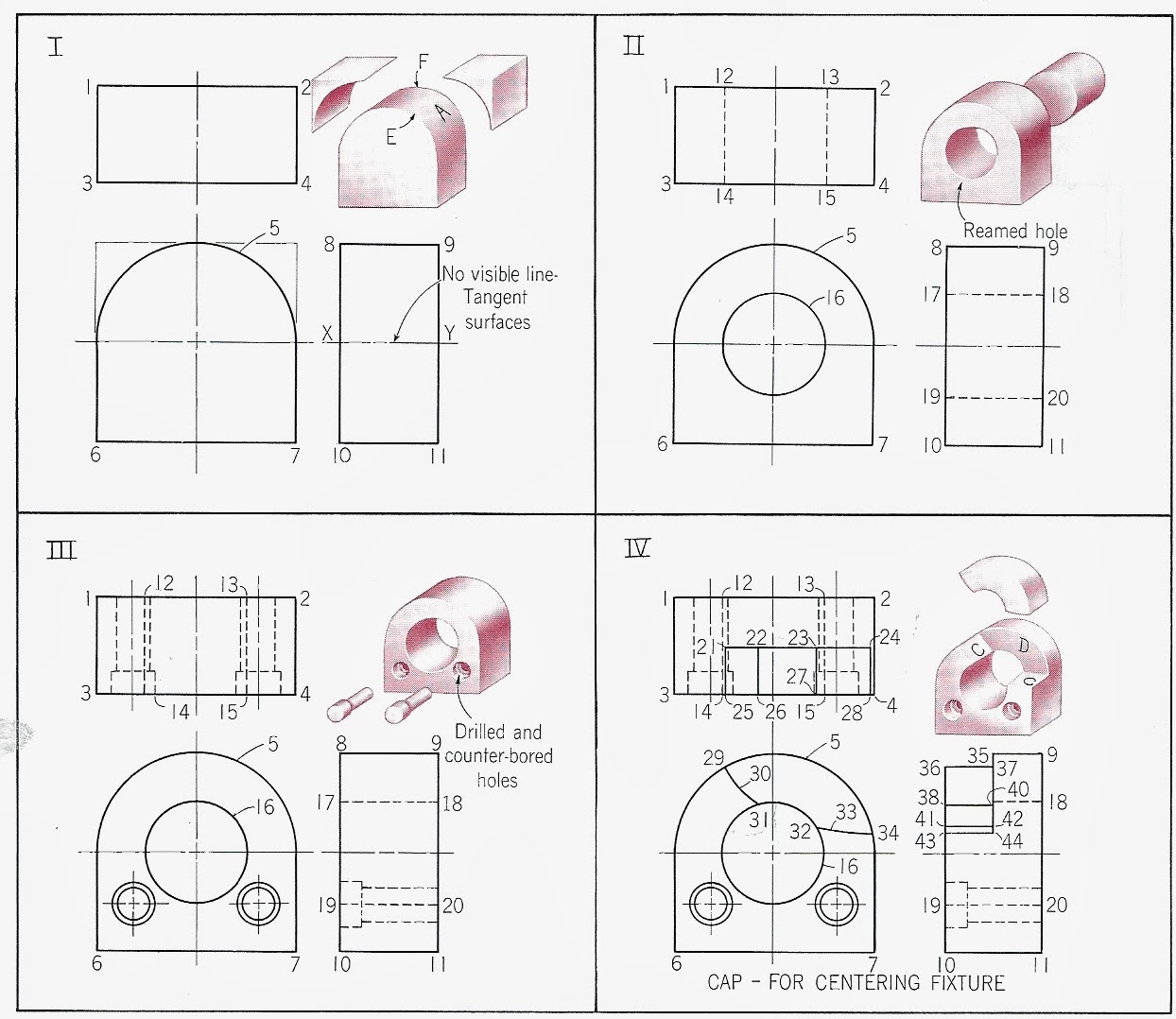
4 steps for Machining a Cap - Cylindrical Surfaces
Deformities of Cylinders:
machined cylinders that have sections cut away to create normal planes.
Cylinders and Ellipses:
Cylinders and Ellipses:
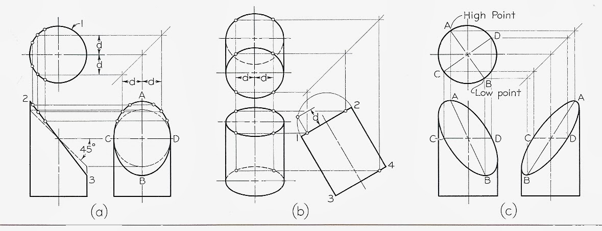
(a) ellipse = cylinder cut on an inclined plane. Looks like circle from above, ellipse from the front, line from the side.
(c) cylinder cut on an oblique plane creates ellipses in two views.
(c) cylinder cut on an oblique plane creates ellipses in two views.
Intersection of plane with quarter-round molding (a), and curve molding (b).
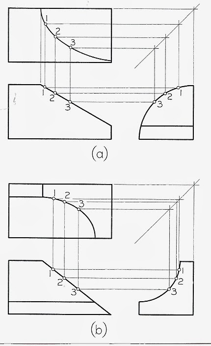
Use sufficient points to create smooth curve:
(a) curve tangent to plane = no line
(b) surface intersects curve = line
(b) surface intersects curve = line
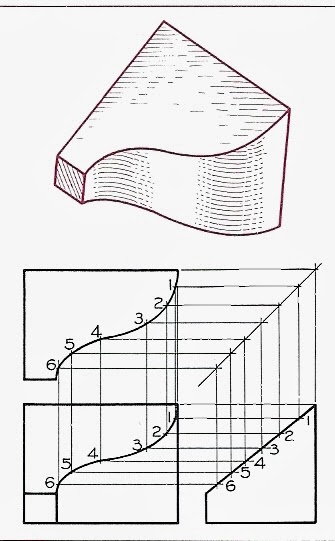
Intersection of 2 cylinders:
(a) prism is narrow, curved intersection is insignificant and ignored
(b) prism is larger, intersection is approximated.
(c) intersection is large enough to justify constructing a true curve.
(d) cylinders are the same diameter, ellipses appear as lines.
Example Intersections
(b) prism is larger, intersection is approximated.
(c) intersection is large enough to justify constructing a true curve.
(d) cylinders are the same diameter, ellipses appear as lines.
Example Intersections
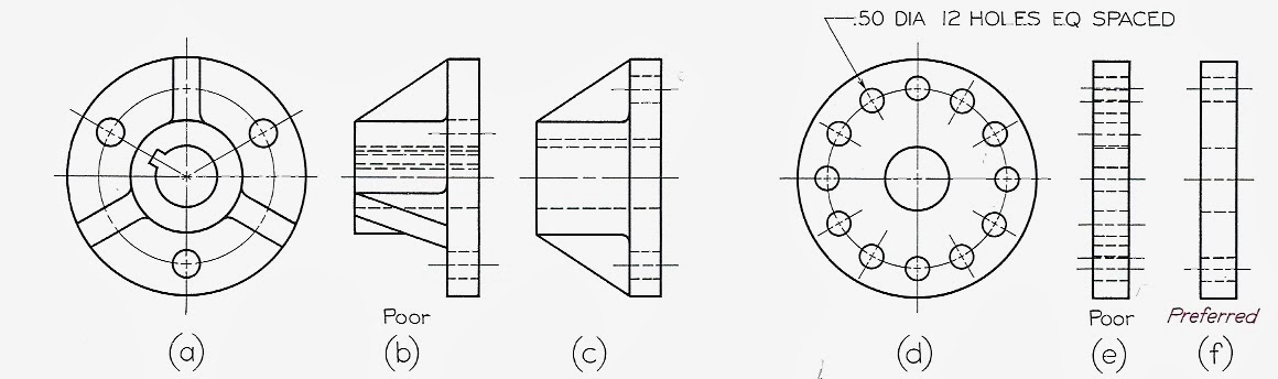
How to Represent Holes:
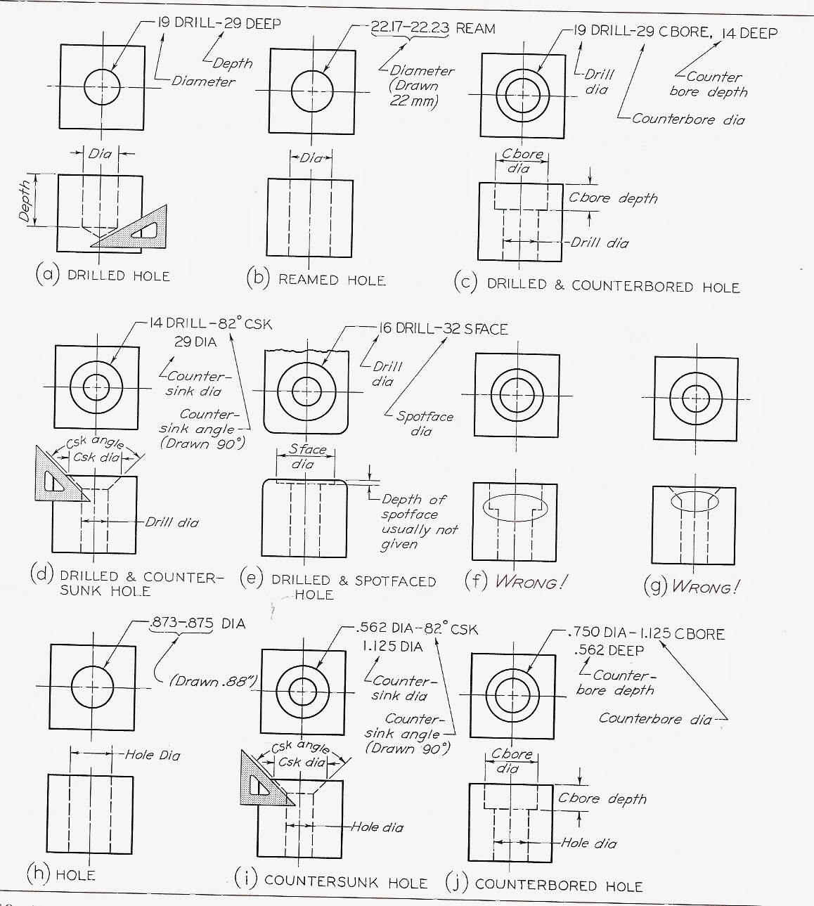
- specify hole sizes by diameter (never by radius)
- diameter given first, followed by the method (drill, ream, etc.)
"through hole" - hole drilled through a member
"blind hole" - hole with a specified depth (depth includes only the cylindrical portion)
- tolerances are ignored in diameter size.
Rough and Finished Surfaces:
- diameter given first, followed by the method (drill, ream, etc.)
"through hole" - hole drilled through a member
"blind hole" - hole with a specified depth (depth includes only the cylindrical portion)
- tolerances are ignored in diameter size.
Rough and Finished Surfaces:
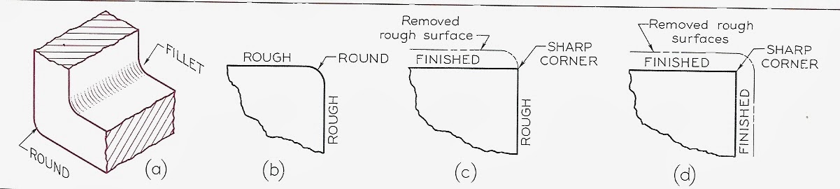
Fillet - rounded interior corner
round - rounded exterior corner
avoid sharp corners - they are hard to produce, and a source of weakness and failure.
round corner - means both surfaces are rough
sharp corner - means one or both surfaces are machined.
Runout: Fillet between plane surface and cylinder
round - rounded exterior corner
avoid sharp corners - they are hard to produce, and a source of weakness and failure.
round corner - means both surfaces are rough
sharp corner - means one or both surfaces are machined.
Runout: Fillet between plane surface and cylinder
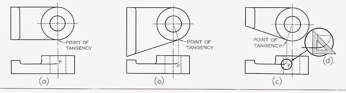
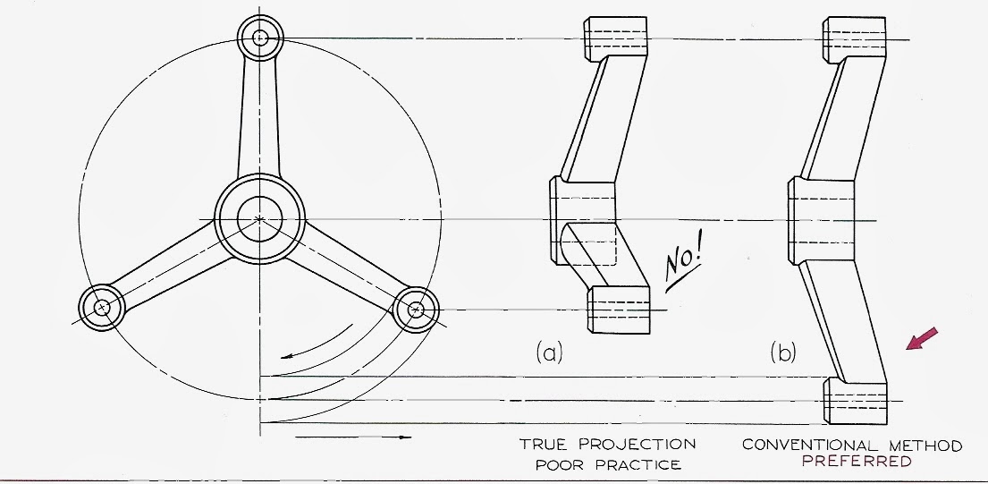
Conventional Fillets, Rounds, and Runouts:
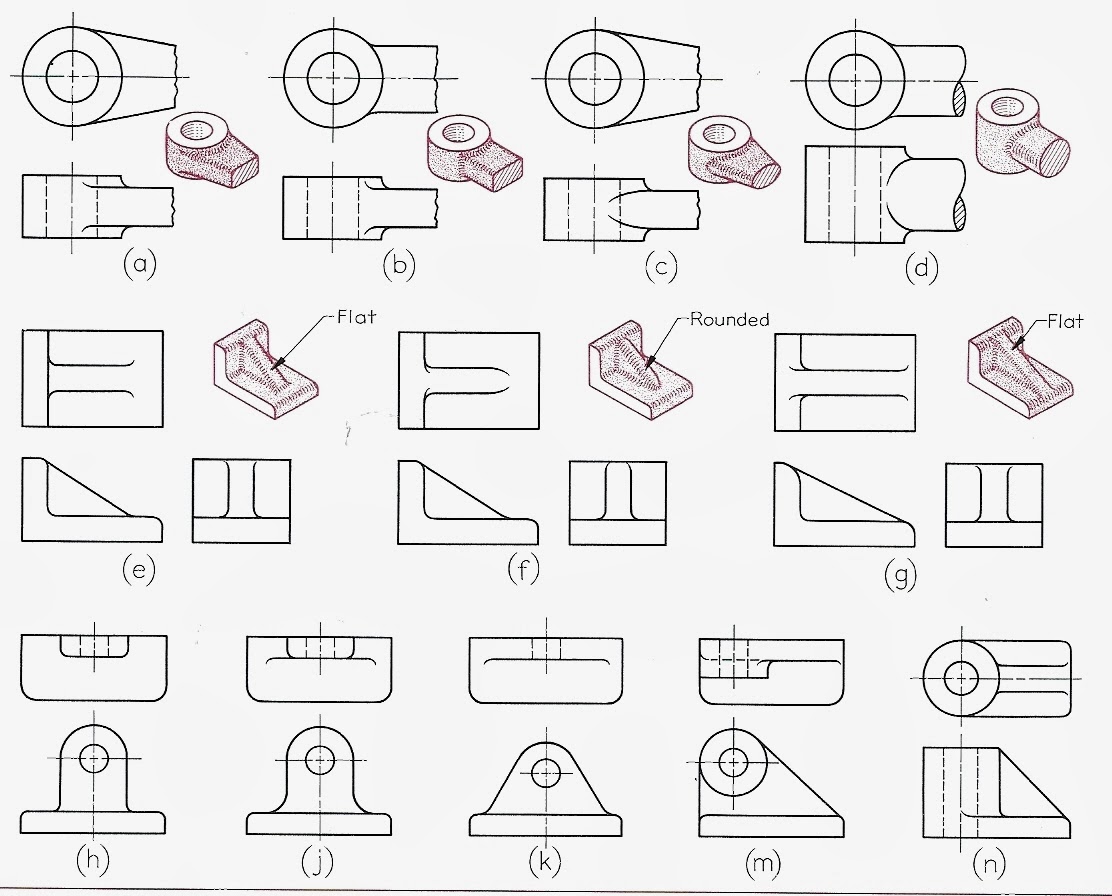
Rail:
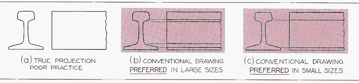
Rounded filleted intersections eliminate sharp edges and make it difficult to present a clear shape description... true projection can be misleading.
(a) no lines were added for filleted edges - misleading
(b), (c) lines added where the intersection of the plane would be if it were not filleted.
Conventional Edges:
(a) no lines were added for filleted edges - misleading
(b), (c) lines added where the intersection of the plane would be if it were not filleted.
Conventional Edges:
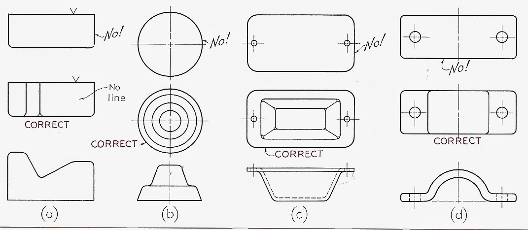
Incorrect, and correct way to represent filleted edges.
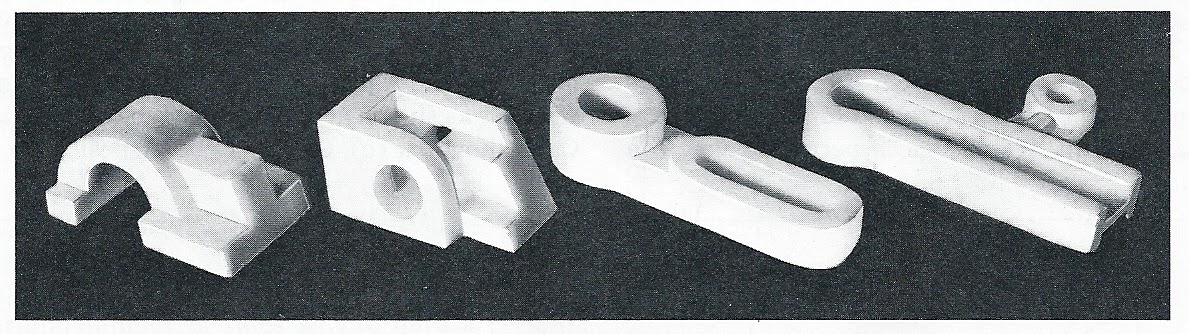
Right-Hand and left-Hand Partssymmetrical parts that function in pairs
LH - left hand part
RH - right hand part
Right-Hand and left-Hand Partssymmetrical parts that function in pairs
LH - left hand part
RH - right hand part
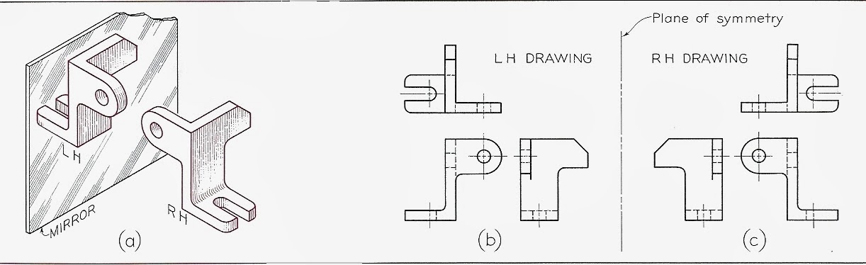
(a) image in the mirror is the other part.
(b), (c) Plane of symmetry
turn the paper over, and trace the back of the image = drawing of the opposite part.
First angle projection - view object from inside the box
Third angle projection - view from outside the box:
(3rd angle projection - ASME Y14.3-2003 - US standard is 3rd angle)
First angle projection
First angle projection compared to Third angle projection:
US, Canada, some of England - 3rd-angle projection is standard
the rest of the world - 1st angle is used.
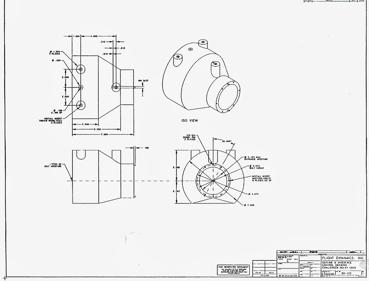
Example CAD drawing
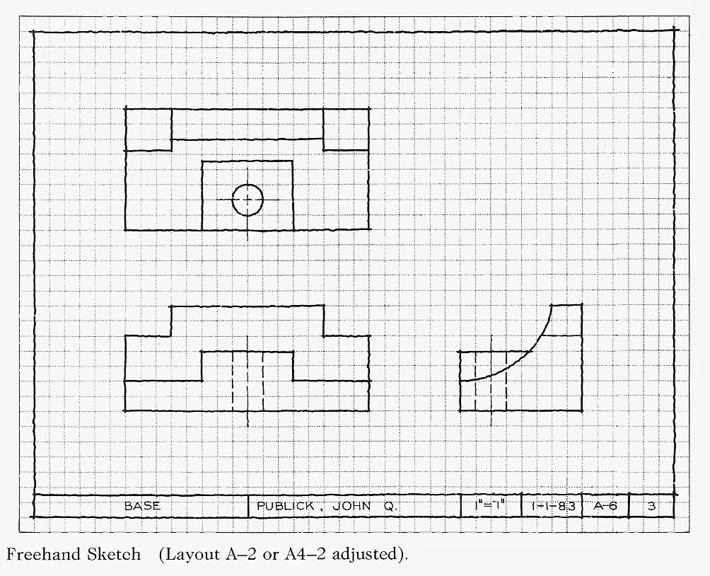

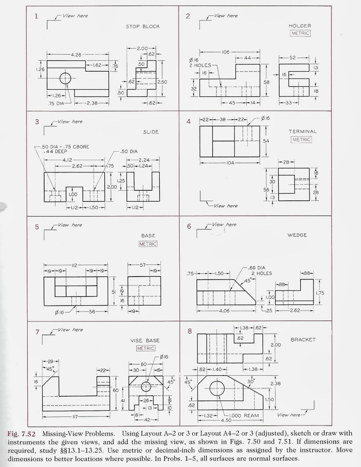
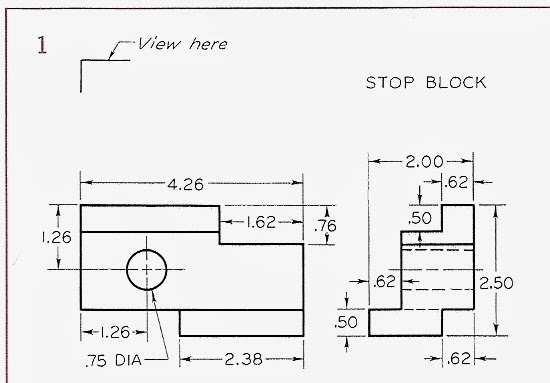
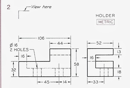
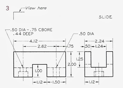
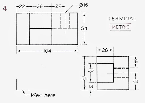
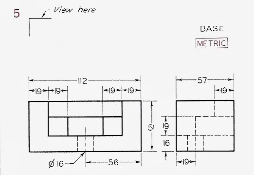
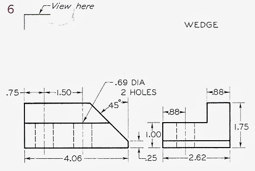
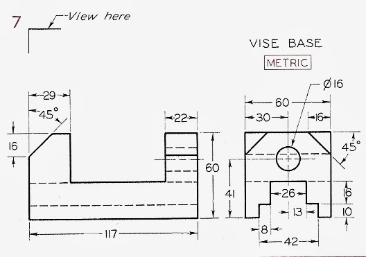
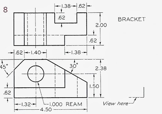
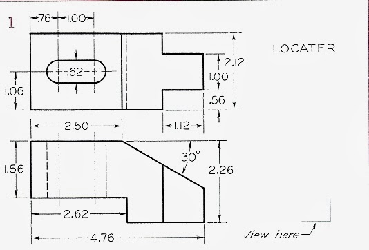
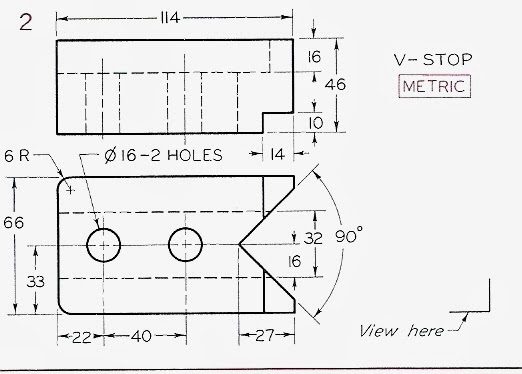
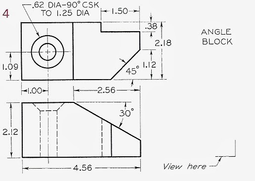
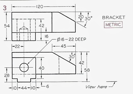
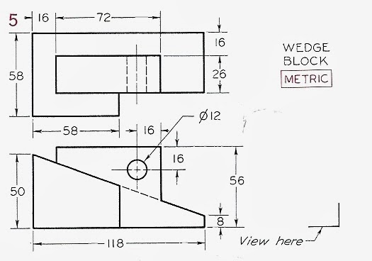
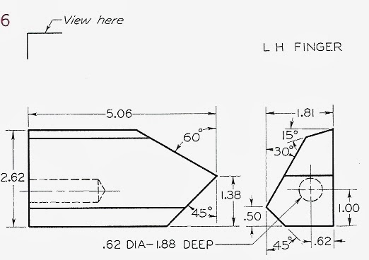
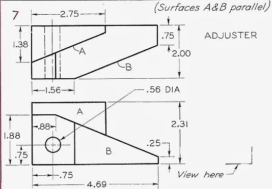
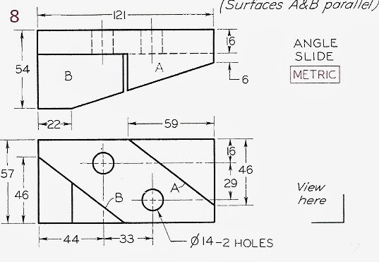
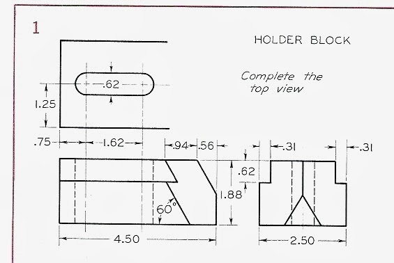
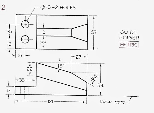
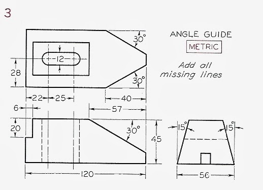
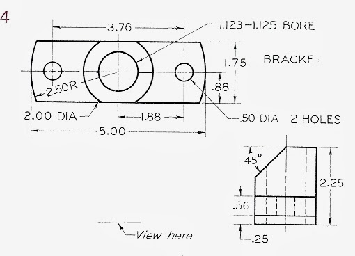
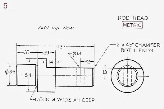
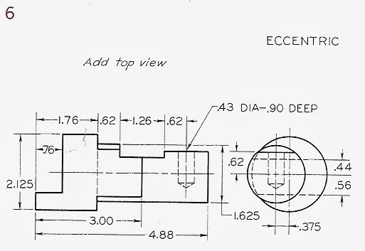
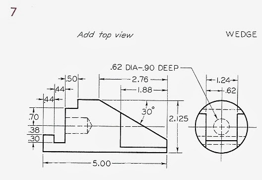
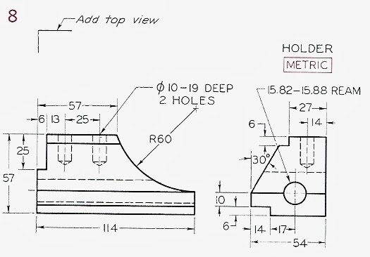
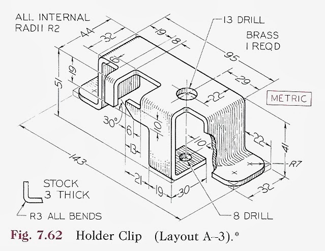
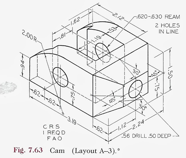
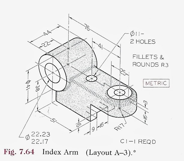
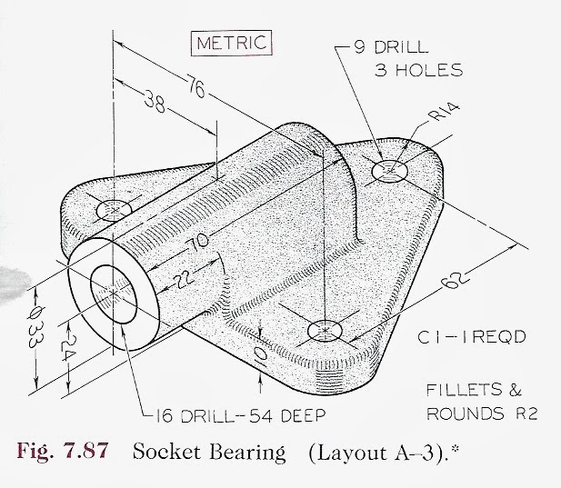
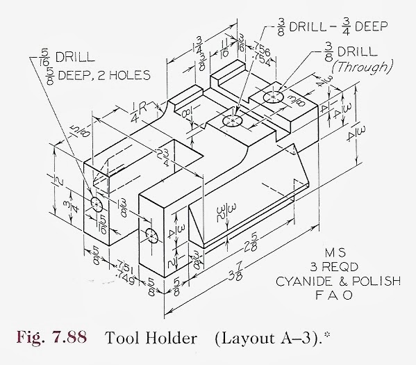
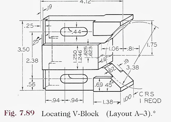
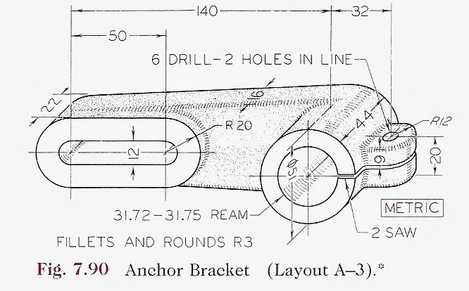
Example exercises: