Finish up AutoCAD before starting Inventor!
Inventor
Autodesk modeling software that is very similar to SolidWorks and SolidEdge
Download the "Inventor Professional" version for free from:
http://www.autodesk.com/education/free-software/inventor-professional
Trouble with the instal? Chat with AutoDesk -
https://www.autodesk.com/education/support/edu-contact-us-form
Inventor is used for:
Design and visualization
Simulation
Stress Analysis of individual parts and assemblies
Dynamic Simulations - driving loads, friction, vibrations etc.
Inventor File types
1. *.ipt for individual parts
2. *.iam for assemblies
3. *.idw for drafting docs
Files can be imported or exported as *.dwg
4. *.ipn – for exploded renderings of assemblies & presentations (not in LT version)
Getting started:
Open "Inventor Professional"
- make sure you are using the professional version as the limited version is missing some of the tools
Start by creating an .ipt file:
rather than choosing the generic part, decide what units you would like to use for entering dimensions by choosing a specific template:
Get in the habit of saving your work from the start!
File → save
Explore everything under "File"
explore export options to create 3Dpdf's and for 3D printing -
The 3D pdf's are pretty neat, but require Adobe to view.
AutoCAD →InventorPro
You can also open your dwg files from AutoCAD
If you want to quickly view a file but not edit it, use "Open Dwg"
To change dwg file into ipt file, a few more steps and some patience are needed.
File → Open → Import DWG → (select DWG file you previously created) → Default AutoCAD Configuration → Next → All →
Import destination options: Change to "3D solids" → New Part (not new drawing), wires to 3D sketch (not 2D sketch), standard ipt template.
~~~~~~~~~~~~~~~~~~~~~~~~~~~~~~~~~~~~~~~~~~~`
Getting started with a new ipt
Click 2D sketch → start 2D sketch
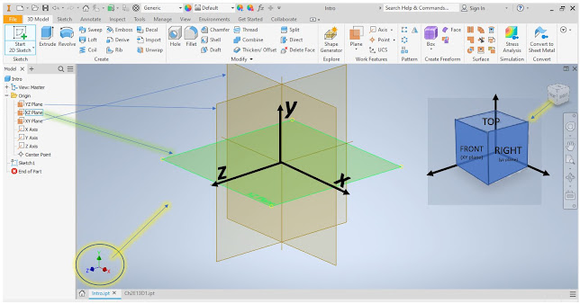
Study the orientation of the x,y,z coordinate system and how it relates to your view cube.
Click on one of the brown 2D planes, in this example I will start on the "xz" plane, or "Top" view from the view cube.
Click 2D sketch → start 2D sketch
Read the description under "start 2D sketch"
click on the horizontal flat plane to start drawing.
Have a look around in the "Sketch" toolbar, Expand all of the options under each of the basic shapes, Hold your cursor over items in the ribbon for directions.
No command line in inventor, so you will need to become familiar with the "ribbon" or buttons along the top of the screen.
Try out your mouse
- Use scroll wheel to zoom in and out,
- Cntr+ click mouse wheel to pan around screen
- double click wheel to center and zoom to see drawing
- Shift-middle mouse click: Rotate model
- Shift - right click: Select
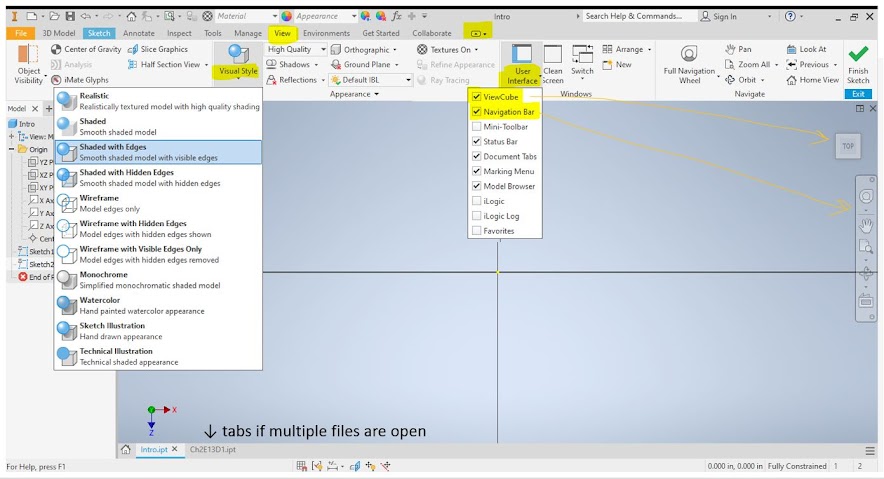
Use the view cube (just like in CAD) rotate "TOP" to be right side up instead of upside down. (Inventor starts upside down for some reason)
View→Nav Bar to bring up the same tools you had in AutoCAD
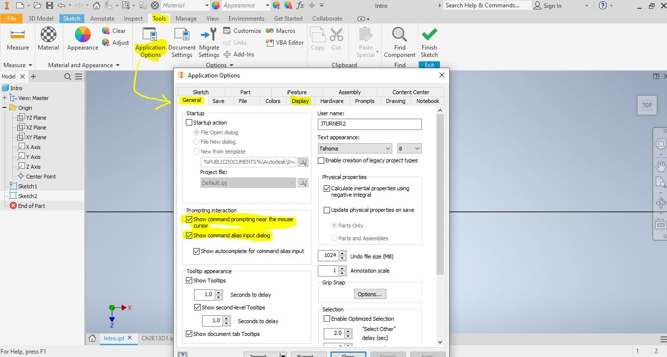
Tools → Application options → add command prompt (might be helpful, turn it off if it is not helpful), change display settings if needed.
Experiment with one of the WS's out of the book
The following is a more challenging example, but if you get through it, you will have a good understanding of how to use constraints, and basic drawing and extruding tools. If this gets too frustrating, choose a worksheet you have already created in AutoCAD and are familiar with .
We will create a 2D sketch → then extrude→ 2D sketch on next layer → extrude etc.
like making a layered cake!
To make 2D shapes,
- First create randomly sized shapes and lines
- Then constrain and dimension everything to the correct size
Rotate your drawing area with the ViewCube so that "Top" is right side up.
Draw a rectangle centered on the origin,
dimension the sides to 2.5 and 1.875
Draw a circle off to the side
making sure it is not snapping to anything, D = 0.625
Constrain the circle, first to the side of the rectangle, then to the top.
Add another circle centered on the first D = 0.125
Draw in construction mirror lines, and mirror your circles to the 4 corners of the rectangle
Draw circle around the entire thing:
Constrain the large circle to the smaller inner circles:
Use the trim tool, then finish your sketch
Extrude up 0.1

Notice the files being created along the left hand side of your work area
Start a new sketch on the top surface of your older sketch:
Use project geometry to trace the previous shape and give your self something to snap to:
Start drawing circles again! D = 0.625
Add lines along the top and the bottom, and then trim.
Extrude 0.3125, done with Layer #2!
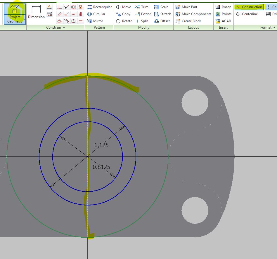
Start a new sketch on top of the older ones:
D = 0.1875
New sketch:
Create construction lines:
Create a circle off to the side, then snap it into place using your construction lines:
Create another construction line joining the centers of the holes on the sides:
Add another circle D = 0.19
Mirror
Lock everything into place
Then create a LONG line off to the side.
Constrain the line to the circles:

Mirror
Trim!
Extrude 0.375
Turn it over, and create a sketch on the bottom
Change the direction of your extrude to create a hole instead of a solid.
Find your gasket sketch in the left hand menu, and copy it onto a clipboard with a base point.
Open up a new part, save as a new name
Ctrl+C → and Cntrl+V to copy and paste 2D sketch in
Extrude your gasket 0.0625
Threaded fastener
Remember that frustrating helix command in AutoCAD? This is much better!!
Inventor as libraries for common thread types, and other parts. (We will explore gears, cams, springs etc. later on which are located in assembly files)

Assembly
If you made it this far, explore assemblies!