Start with a sketch of your 3D cube:
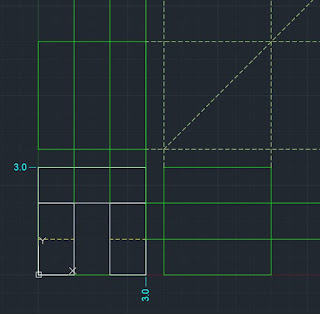
Sketch the Top, Front, and Right hand views of the cube:
Make sure each side lines up with the other sides, add hidden lines, and decide on dimensions in your sketch:
Sketch → CAD
Start in the construction layer, and create a basic cube:
Rec → start rectangle command
Specify First Corner → 0,3
Specify next corner → 3,0
Use the "copy" command to copy the front view up to the top and over to the right hand view:
It is usually easiest to fill in the front view first (you will see why in a second):
The construction layer can be turned on or off to more clearly see the visible layer:
Click on the hidden layer, and add hidden lines:
Change back to construction lines
Send RAY's out from the front view to provide a grid for the top and right views
(This is why it is best to create the Front view first)
Create a folding line to show how features wrap around from the right side to the top:
Switch back to the white visible layer, turn all your snaps on, and fill in the rest of the views!
If it helps, move your coordinate system around:
Notice the location of the x,y coordinates.
Type in UCS (for User Coordinate System)
Specify origin of UCS or[go back to the "world" or original location] - type in the coordinates, or click on the corner of the cube you want to go to.
Specify point on x axis (pull x axis to where it needs to go)
Specify point on xy plane (pull y axis to where it needs to go)
DIMORD → Labels coordinates to help think through dimensions.
DIMSTYLE → change the style of your dimensions.
We will go through more dimensions and tolerances in Chapter 6. Dimensions are usually not used in the model space, but they can be convenient when keeping track of the location for everything.
VIEWPORT → Draw a large rectangle (yellow area) in a layout with your title block.
Click on "Model" and "Paper" space.
Titleblock → copied into paper space
Drawing → can be viewed and manipulated in model space.
Go back to that 2D scribble page to experiment with everything in the "Draw" and "Modify" tabs. You should be good at using "Trim" (be sure to <select all> by hitting enter for that one), move, copy, mirror, try them all out!
Next week we'll start 3D!!!
** Note: Yes, AutoCAD now has the command "VIEWBASE" which automatically creates orthographic projections from the 3D object for you. It is good practice to create a few ortho views on your own though to get used to them before letting AutoCAd do all the work.
Try out some WS's from Chapter 2, but also create some of your own objects - create your own unique cube. Try out one of the pieces of your project in CAD - 3D objects are most commonly extruded from 2D drawings, start in 2D, then we will extrude everything up into 3D.


