Make a complete set of working drawings for a simple assembly Your set of working drawings will have:
a) An exploded assembly drawing with a parts list, balloons with leader lines.
b) Individual parts with dimensions and tolerances.
Pull up one of the assemblies that you created out of chapter 9
Change the color of each of your parts to more easily distinguish them:
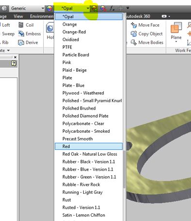

hold down the Cntr key to select multiple surfaces when assigning materials.
New → Presentation

Create View → open up your assembly file

You can try to "automatically" explode it, but this does not always work out so well (especially when you have a lot of parts).... so select "Manual".

5. Tweak Components →Components →choose a part → Direction →click on a face and a direction, grab and pull it away, create a trail →"close" when you are done.


Note: You can select more than one component at a time, so you can move screws together etc. and you can also move in one direction, then click "x , y, or z", and move in another direction before closing.

6. Click "animate" to see your components coming exploding or coming together, then save it.

Create a set of working drawings
Different file types:
***.ipt - for making parts
***.iam - for assembling parts together
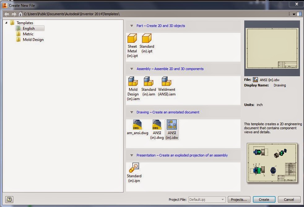
***.idw - for making a drawing / baseviews / page for printing.
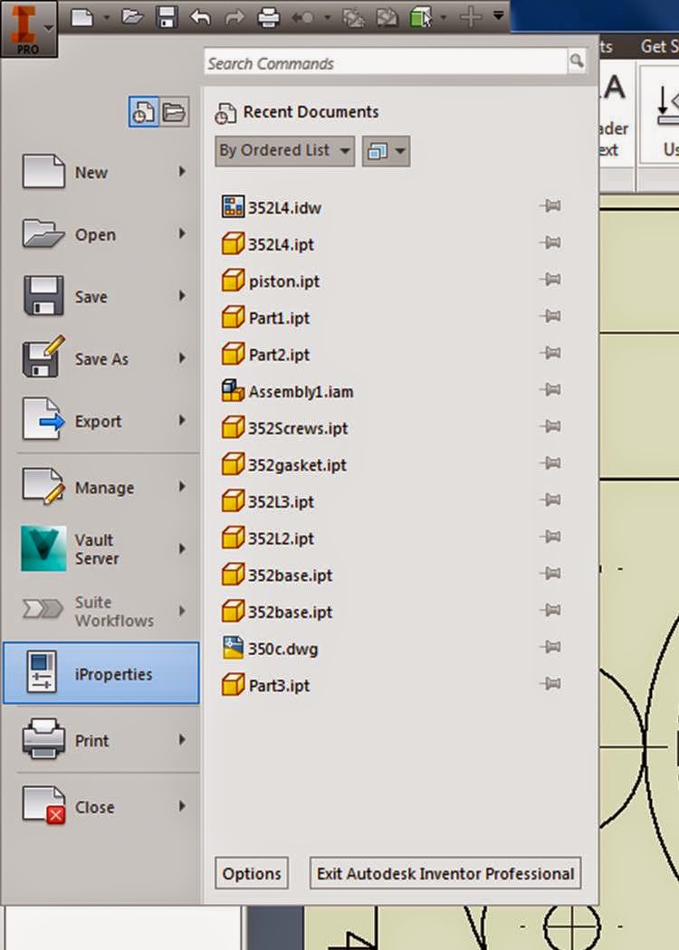
From the big red I, select New, then select standard drawing *.idw
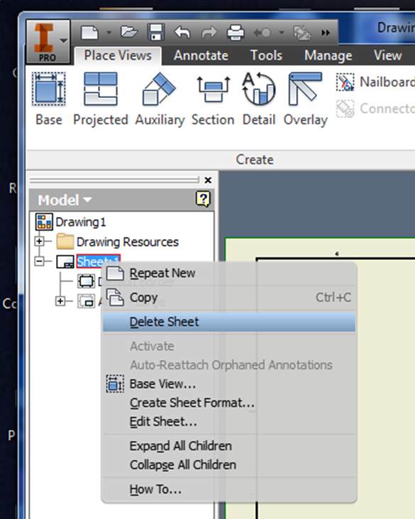
Inventor will pull up a default page with a generic title block for "C" size paper. We don't want C paper, so right click on your model bar, and delete sheet 1.
Hit the [+] beside drawing resources, the [+] beside borders, and the [+] beside Title Blocks, select ANSI A titleblock and default border by double clicking on them.

This will give you a standard title block and border.
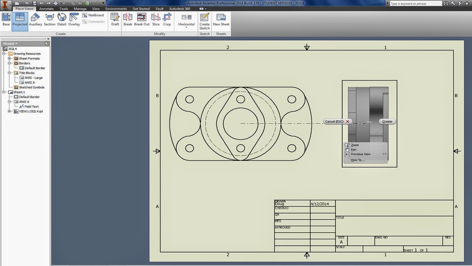
Place Views Tab
- Use Base(view) just like in AutoCAD, pull up your file,
- change the scale,
- choose the orientation of your assembly (bottom, top, etc),

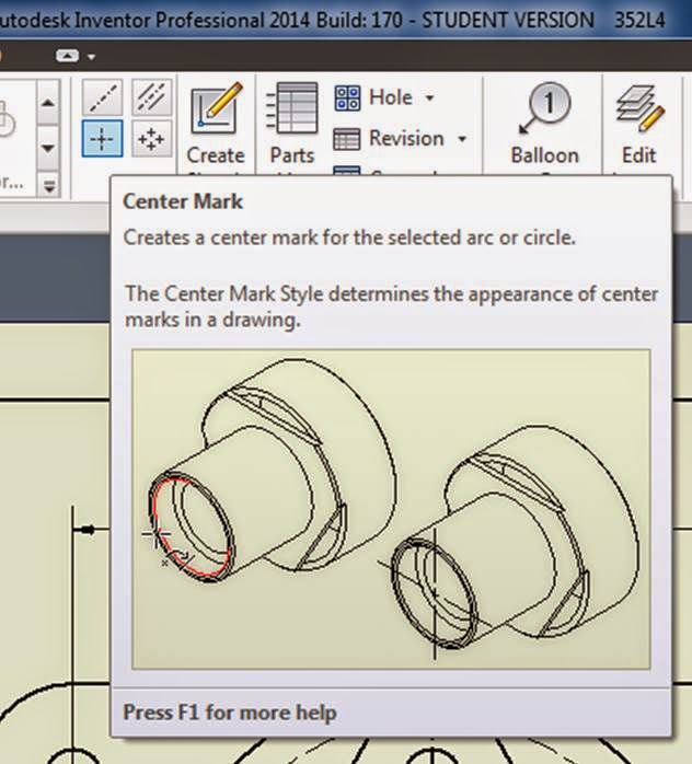
You can create additional projection, and section views after you hit "Esc." by clicking on the icons in the ribbon.
Projected Views:
Click on Projected, click on object, pull out a view, Left mouse click to place, then right click to create.
Sectional Views:
Click on "Section"
Draw line where you want to section it.
Right click, continue.

Set your scale, change the Style, etc. then hit ok.

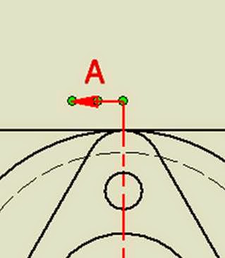
You can click on the green dots to move your A-A sectional line around after it is created.
You can also select a view, and move it around until it is centered.

Annotation TAB:
This is where all of your dimensioning tools are.

Skim through the options in the Dimension menu as you are creating dimensions.

Right click on the dimension, (hold down shift to select more than one dimension) Edit dim style, scroll through all of the options.


Changing arrowheads:
Hover over the dimension
When green balls appear, right click,
Choose "Edit 1st / 2nd arrow"
Change Precision:
Double click on dimension, when box comes up just type in the number of sig figs you want.
Title Block:
Click on big I
> iproperties
>summary - fill in name etc.
>project - fill in what is needed (you don't have to type something in to each area)
> Apply, close
