Cutting plane:
- Depends on shape of object
- Usually parallel to one of the orthographic planes
- Often along a centerline
- Linetype for cutting plane:
↓ ↓
A A
- Cutting lines take precedence over other lines
- Arrows at the end indicate which part of object was removed
- Labeled with letters at both ends
Rules for Sectioning:
- Omit hidden lines in sectional views
- Cut surfaces are shaded or "hatched"
ANSI standards for hatch patterns:

Typically Hatch patterns are:
- parallel
- properly spaced
- oriented at an angle that is not parallel or perpendicular to the object (30°, 45°, or 60°)
- slightly thinner lines than object lines
- Adjacent components hatched at different angles
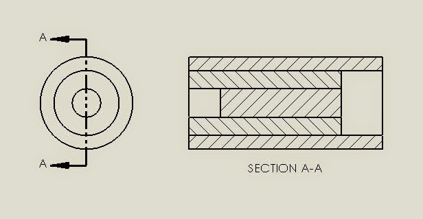
"Full" Cross-Sectional View:
Plane that cuts vertically through the center of the bloc:


Half-Section
(Half of a full section = 1/4 cut away)
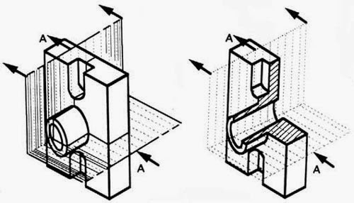
Sectioning Objects with Holes, Ribs, Etc.
The cross-section on the right of figure 22 is technically correct. However, the convention in a drawing is to show the view on the left as the preferred method for sectioning this type of object.
Offset Section:
For objects whose features do not all lie along center line

Revolved sectional view:

Sectional Views usually replace one of the views in an orthographic drawing


~~~~~~~~~~~~~~~~~~~~~~~~~~~~~~~~~~~~~~~~~~~
Spend a few moments skimming through some of the examples in chapter 4!!
The best way to make this is to draw it with the same orientation as shown in the worksheet.
Start with the Front view

To draw on the front, rotate your coordinate system so that the xy plane is on the front.
UCS (User Coordinate System)
Specify origin of UCS or [Face, Named, Object, V, W, X Y Z Zaxis] → click on "x"
Specify rotation about X axis →90
Start by drawing the circle on the front.

CIRCLE
center point → 6,4
radius→3
CIRCLE
center point → 6,4
radius→4

PRESSPULL
select area between the two lines

extrusion height →12
Esc → get out of presspull
UCS → W
change your UCS back to the world coordinate system, and see what you have on the front.

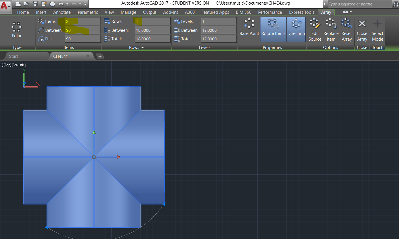
Array → Select cylinder→
Polar→ center point 6,-6,4
Items→2, Between→90°
Before hollowing out the tubes, add the top!

UCS - W, look to see where the front view is, and where the top view is
UCS - 0,0,6 orient x,y, axis to easily draw the top circle (z up)
This is just a little below the top so that the top piece will come down into the corners.

Look from the top view
Circle, 6,-6, r = 4

Extrude→mode→solid→5

UCS→W
UCS→x→90°
CIRCLE→6,4→3
Extrude→solid→push all the way through
Union→Join top part and bottom tubes together

Subtract→ the piece you want to keep minus the piece you want to get rid of.

UCS→Y→90
Circle→-6,4→radius 3
EXTRUDE→ push all the way through
SUCTRACT→ get rid of the tube in the center


Now, move the UCS and carve out the top!
UCS→W
Look at which side is the front
UCS→x→90
CIRCLE→6,10→1
SUBTRACT


ucs→W
UCS→Y→-90
RECTANGLE, 8,-4→12,-8
EXTRUDE, SUBTRACT

UCS→W
Check your orientation, is the front in the front? If not, use 3DROTATE
VIEWBASE→model space (enter)
Leave room in the center for sectional views!

VIEWSECTION
Select parent view→ click on front view
Specify start point→center of the top
Specify next point→center of the bottom
done (enter)
right click on text→quick properties→text height→0.15

VIEWSECTION

Notice that each of these sectional views look the same (just rotated). Which view would be the best to include?
Sometimes sections views help show how two different parts come together. Experiment with making a hinge!

First, create a hinge.


You can decide on your own dimensions and styles, just make it symmetrical, and create two interlocking pieces.


Create full sectional views, snap to the center of your objects!
Click on one of your viewbase views to select it.
Notice the new "Drawing View" menu
Click on the arrow under section view

If you cannot find the sectional views in the ribbon, type "Viewsection" into your command line, and follow the prompts.

Click on the text labeling your section, use the blue handles to drag it to a good place on your page.
Right click on the text, choose "properties" and then change the text height etc.


Remember, you need to be in model space to change the orientation and type of view you have in model space through your viewport.

Annotate →Dimlinear, etc.

In another layout, explore the "Detail" views. "detail" is in the ribbon in the Layout tab, right next to sectional views. Start with viewbase again, and then select rectangular or circular portions to create a detailed view.
VIEWDETAIL
select parent view
boundary (enter)
boundary type → circle

Skim through the rest of the tools in the Layout tab:


Try out a detail view:

~~~~~~~~~~~~~~~~~~~~~~~~~~~~~~~~~~~~~~~~~~~~~~~~~~
Work through some of the other sectional views in chapter 4.
pgs 161-181
~~~~~~~~~~~~~~~~~~~~~~~~~~~~~~~~~~~~~~~~~~~~~~~~~~~