
Use radius = 1, 2, and 6
Polar array for outer holes
presspull inside to 8 and outside to 4
VIEWBASE
VIEWSECTION
Create sectional view of inside

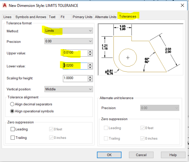
Set up some tolerance types:
DIMSTYLE
set everything in dimstyle like you did before - precision, arrow type and size, txt size etc., then look at the tolerance settings:


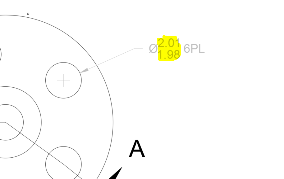
Try out your newly created dimension

create a new DIMSTYLE for each of the different tolerances:


experiment with some of the other tolerance settings:
QLEADER
<settings>
Try out tolerance


To add a Datum label - just type "A" in Datum 1, hit "ok"
>Enter Tolerance Location > click where you want your label to go. You can move the box around later if you need to.

To automatically add a tolerance label with a leader line:
type QLEADER<settings>


Note: You might have to re-size your datum arrows and text - just right click on it, select properties, and change it.

Type in "QLEADER", choose <settings>, tolerance, choose your arrow head, draw in your leader line,
Click on symbol, and choose what you want to do.
.

Table of symbols from your book:

Next, add your tolerance in, and Datum reference:

It will create a box with your tolerance symbol, values, datum points, and anything you filled out.

Create a dimension, Double click on it, and edit it.
TEXTEDIT also allows you to edit text.
Assignment: Try out page 307
Create the 3D object, then create the Base Views from model space in a layout, then add in all the tolerance boxes.

Don't forget your polar array commands!


(Fill in the blue boxes with the correct symbols and tolerances.)

Fill in the other tolerance worksheets in Ch7 too.
If you get done early, work on your semester project!