Arch Bridges, Drawing with Equations in Inventor, Stress analysis including gravity
exploring some more tools in Inventor.

Rules of thumb for creating arches:
For Circular arches - avoid flattened arches
pg 26: 1/9< rise/span=H/L <1/6 (1/4, 1/3)
rise/span ~ 1/7.5
Statics of arches link
Statics of arches link


The taller the bridge is, the smaller the force in the truss.


If H/L does not exceed 1/7.5, what is "H" for your given L?
example:
for a bridge using only one arch to span 1000m:
L = 1,000m (0.62 niles)
example:
for a bridge using only one arch to span 1000m:
L = 1,000m (0.62 niles)
H = (1/7.5)*1000 = 133.333m (437.445 ft)
Use Excel or Mathematica to test out your equation!
Use the 2D equation to create the arch with Inventor: link
Start a sketch:

Read instructions under the equation curve

Enter equation:

x(t): (4*(1000/7.5)*t/(1000^2))*(1000-t)
y(t):t
tmin:0 tmax:1000
check your view cube - are you right side up?
Modify→Offset your line to create a 2D area to extrude:

Read through:
https://knowledge.autodesk.com/support/inventor-products/troubleshooting/caas/sfdcarticles/sfdcarticles/Importing-point-data-into-sketch-s.html
You can import points from a Microsoft® Excel spreadsheet into a 2D sketch, 3D sketch, or drawing sketch. You can use the points to represent items such as inspection points, locations for spot welds, and points on a spline.
The points are automatically created in the sketch according to the coordinates specified in the spreadsheet. The origin of the sketch is used as the origin for the imported point data.
Keep in mind that the points are not associative. A geometry that is based on the points will not be updated if the points are moved or deleted.
The Excel file containing the points should be in the following format:
- The table of points must be in the first worksheet of the Excel file.
- The table always starts at cell A1.
- If the first cell (A1) contains a unit of measure, it is applied to all the points in the spreadsheet. If no unit is specified, the default file units are used.
- Columns are defined as follows:
- Column A is for X coordinates
- Column B is for Y coordinates
- Column C is for Z coordinates
- If the spreadsheet contains Z axis values, only X and Y axis values are imported into a 2D sketch.
- Cells can contain a formula, but the result of the formula must be a numeric value.
- On the Sketch panel bar, click the Import Points icon.
Insert → points
- On the Standard toolbar, click the Point/Center Point tool to specify either sketch points or center points.
- In the Open dialog box, browse to the folder where the spreadsheet is located, select the spreadsheet, and click Open.
Note: Sketch points are created without constraints. Use the constraint tools to add constraints.
Create a set of data points in excel to help create a truss structure under your arch.
Try something simple to make sure you know where your origin is and how everything works before trying anything complicated!

Create a bridge!
Start simple, then add on to it!


Gravity Stress Analysis:
The bridge has to support it's own weight as well as the added loads that are applied to it.
Environments → Stress Analysis→create simulation→Assign materials, fixed ends etc.
Add a gravitational load.
Environments → Stress Analysis→create simulation→Assign materials, fixed ends etc.
Add a gravitational load.


Sweep:
you need sketches on two orthogonal planes:

sketch #1:

sketch #2:
path starts in center of sketch #1

open up the sweep tool, choose your profile and path.


Warning: The sweep tool can be trouble to use with complex geometries, or overlapping parts. You can try it for cables on bridges, but you will probably run into some trouble...
COMBINE AND SPLIT
Create a 2nd solid object by extruding a box around your pipe

Make sure you are not adding onto your first object - but instead creating a 2nd solid:

you should see the second solid in your model list:

change your materials to "clear" and "glass" so that you can see both of your parts:
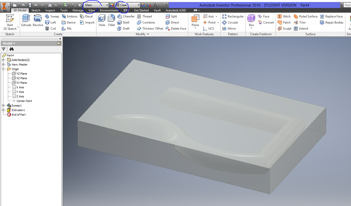
Use the combine tool to subtract part 1 from part 2


Create a new working plane - scroll through all of the options for creating planes:

Each time you create something new, look in your model space to see where it is being created!

Try out the split tool!
Use the working plane as the split tool, then select your solid block.

Check your model list - you just created a new solid by cutting the old solid in half!
Right click on anything in your model menu to turn on and off visibility. Change your materials around so that you can see inside your block.

Skim through your ribbons, and try out any other tool you have not used yet!
Having trouble using something? Just google a youtube tutorial!
Next up - intro to dynamic simulations.
No comments:
Post a Comment