Collection of drawings that provide all necessary information for the construction and assembly of a product.
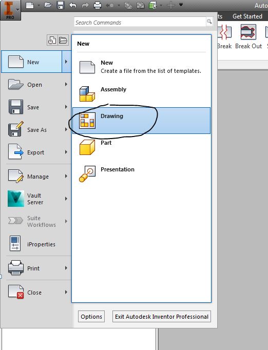
First Open a new→ drawing
there are mm and in drawings - choose the unit that matches what you used on your engine project.
Save it as a *.idw
Inventor Drawing File

i Properties
Inventor files store information about the file such as when it was created and revised, who created it, company name, etc. 
Look around in all of the different tabs, fill in information about your project, and add new categories for any additional information you need to store by just typing in a name, and value under custom.

To create your own custom Page
1st Delete the existing border and title block
right click → delete

Define your paper size and orienation
right click on sheet one →edit sheet

Name your sheet with a description of what is on it. When you have an idw with many sheets, good names for each help organize your work!
Choose a paper size Your page size and orientation should be consistent for all of the pages in your set of working drawings.

Standard Paper Sizes:

Expand the options under the Drawing resources

Add a Custom Border
right click on default border → Insert Drawing border

Try out some different formats to see what everything does -
example 4 horizontal zones and 6 vertical zones creates...

Zones help line up views symmetrically

Once you are done experimenting with the border settings, delete out your experimental borders, and create what you need for your part:


Unless you have a lot of small parts, 2 zones are usually standard.

The numbers inside the border are outside the printable range and are only used for placing views.

Create a custom Title Block
right click on Title Block → Define new Title Block

This brings you into the sketch environment - draw rectangles, lines, just like we did in AutoCAD


Often company logos are added into the Titleblcok

Use your snipping tool, save an image to add into your titleblock. Use whatever image you would like!
Image → draw a rectangle for where you want your image to go

Add text in two different ways:
1. permanent text that will be the same for all parts:


Text that is defined by iProperties:


Remember how to create your own iProperties?
Click on I → iProperties→Custom→type in whatever property you would like to keep track of

Use your created iProperty in the Titleblock

Try out some of the text options like rotated text!

When you are finished, save it -

Insert it into your *idw

If your iproperties do not automatically populate
-open up iProperties, make sure there is something filled in
- create custom iProperties for everything that you have trouble with

Create a sheet for each of the parts in your assembly

Use uniform borders and title block on each sheet


add titleblock

Fill in prompted entries
- if you would like more prompted entries in your title block, just double click on your title block and edit anything you need.


Assembly Drawings:
- usually on the first page in a set of working drawings
Two formats:
collapsed - parts assembled together
exploded - assembly pulled apart
