Layers:
Using layers helps organize your work. Each line and object should be assigned to a layer depending on what it is. Common layers:
Add layers:- select layer properties

Add new layers:

Creates layers for:
- View
- Center
- hidden
- construction
- meter line
You'll need to load the line types, then select one.

Move the layer you are working on to the top:

Now that you have your layers set up, save your file as AcadLayers.dwt

Check under your startup menu - you should now have a new template:
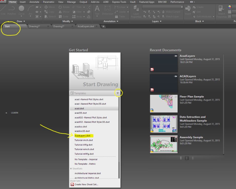
In the future you will not have to create layers every time you start a new drawing, you can just open up this template that has all of your layers set up!
Draw the orthographic views from the worksheets in your book.

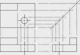
Page 57 is show below to help you through this first one. Note the green construction lines, dashed hidden lines, and solid border lines from the different layers.

Switch between the green layer for construction lines, and a white layer for final lines, and a yellow layer for hidden lines.

You will draw on whichever layer is selected. If you want to change the layer a line is on, just click on the line to select it, and then click on the layer you want that line to be on.
Type in the exact coordinates for all your lines rather than just eyeballing it. We will dimension these - if you did not type in the exact coordinates, your dimensions will be wrong, and you will have to re-do the entire thing.


Note: Make construction lines transparent in the layer properties
Use "Trim" command to delete unwanted lines
Turn on "snap" to draw lines without typing in coordinates

XLINE - creates a line that runs in either direction to infinity - great for making construction lines
DRAWORDER - Allows you to choose which line is on top if lines overlap one another
Use the up arrow on your keyboard, or enter, or space bar to get the previous command you were doing. (instead of typing "LINE" over and over again, just hit enter)
A few (x,y) coordinates:

Dimensions:

Selection tool tip:
Click left mouse button for a square,
Hold down left mouse button for a lasso.
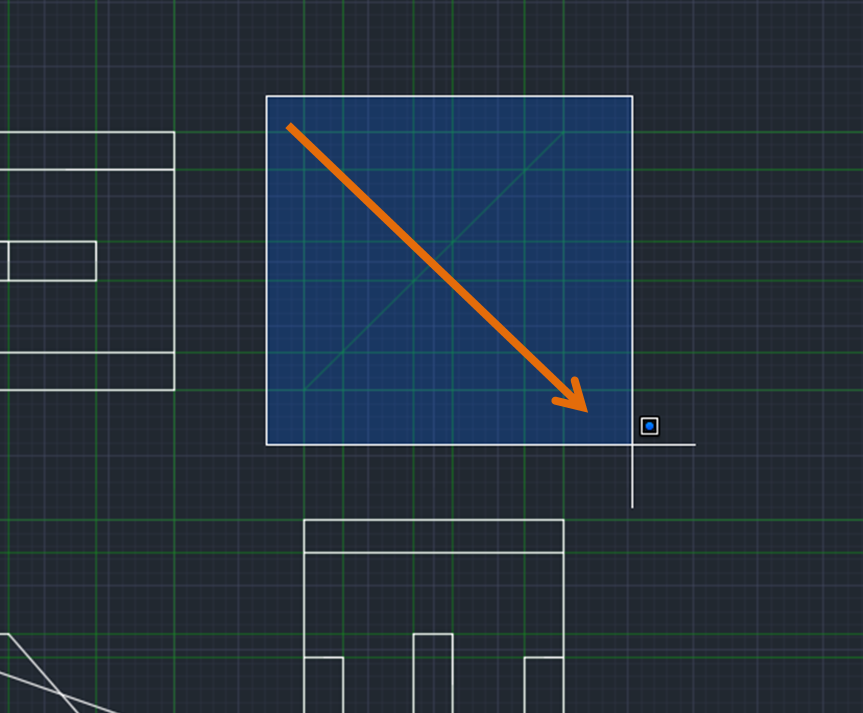
If you select something from the left to the right, it will only include what is entirely encompassed within your selection area:

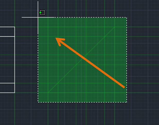
If you select something from the right to the left, it will grab anything that is touching your selection area:

Next - change some lines into hidden lines!
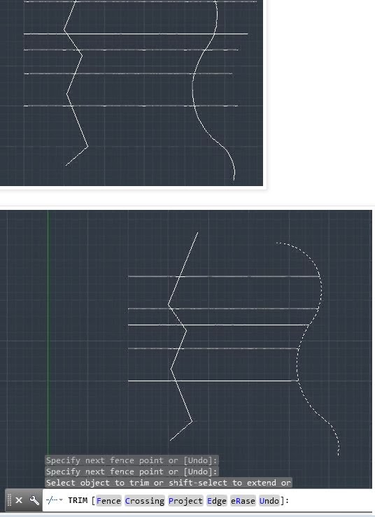
"TRIM" off lines you don't want:
→TRIM
→ <select all> hit enter (this selects your cutting lines)

note: whatever is <inside these brackets> will be selected if you just hit enter.
→click on line segments that should be hidden to get rid of them.


Use your construction lines to add dashed, yellow, hidden lines in the right spots.

Are the dashes too small? Get into your layers box, and change the line type, or type in "LTSCALE" and enter different values (1? 2? .5?)


UCS (enter)
Specify origin (0,15) ← type in the coordinates of where you want the new origin to be
Specify point on x axis → click in the drawing area to orient the x axis horizontally
Specify y axis - click on screen to make the y axis point up.
Need to go back to the original coordinate system? Just type in UCS (enter) then "W" for world
~~~~~~~~~~~~~~~~~~~~~~~~~~~~~~~

Practice makes perfect!
Try the ortho views for another ws!

~~~~~~~~~~~~~~~~~~~~~~~~~~~~~~~~~~~~~~~~~~~~
More notes on CAD:

Applications Menu (Big red "A")

Everything in the work space can be customized - save your work space customizations in your template as well.
Example:
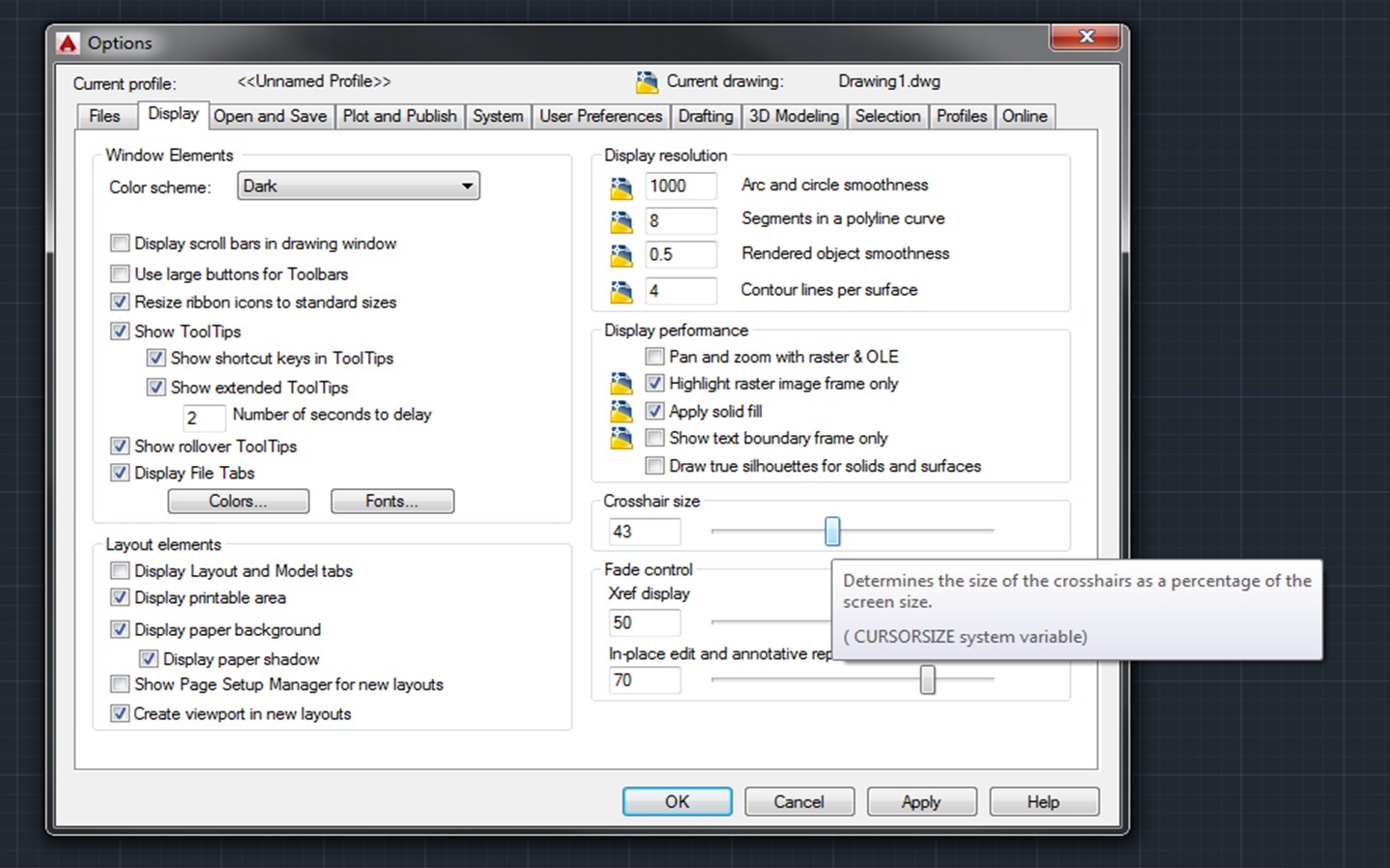
Right click on black screen > Display > set user preferences
If someone messes up all the toolbars and settings
Right click on black screen (or type "OPTIONS" into command line)
Example:
Right click on black screen > Display > set user preferences
If someone messes up all the toolbars and settings
Right click on black screen (or type "OPTIONS" into command line)
OPTIONS> Profiles tab> Reset


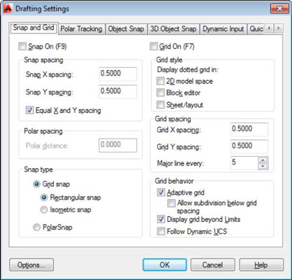
Restricts cursor movement to specified intervals.

GRID Rectangular pattern of lines or dots that covers the entire XY plane of the user coordinate system (UCS). Using the grid is similar to placing a sheet of grid paper under a drawing. The grid helps you align objects and visualize the distances between them. The grid is not plotted.
If you zoom in or out of your drawing, the grid spacing is adjusted automatically to be more appropriate for the new magnification. This feature is called adaptive grid display.
Set the Grid and snap intervals:
ORTHO:
POLARIn polar arrays, items are evenly distributed about a center point or axis of rotation.
OSNAP: Object Snap, Snaps new line etc. to an object.
If you enter -OSNAP at the Command prompt, the following prompts are displayed.
ENDpoint
|
CENter
|
TANgent
|
MIDpoint
|
NODe
|
NEArest
|
INTersection
|
QUAdrant
|
PARallel
|
EXTension
|
INSertion
| |
APParent Intersection
|
PERpendicular
|
3DOSNAP3D Object Snap. Set the 3D object snap settings with 3DOSMODE system variable.
Example options:
OTRACK object snap tracking: Tracks along alignment paths that are based on object snap points.
DUCS Defined user coordinate system ( UCS ) - change the location of the (0, 0, 0) origin point and the orientation of the XY plane and Z axis. You can locate and orient a UCS anywhere in 3D space, and you can define, save, and recall as many user coordinate systems as you require.
DYN Dynamic input provides a command interface near the cursor in the drawing area.
LWT: line weight. Set line weights by layers.
TPY: Transparency, sets different layers to different transparency levels.
QP: Quick Properties, double click on anything to get it's properties box.
SC: Scale
Esc - clear command line
Enter or Spacebar - usually repeats previous command, or accepts <default action>.
[command options] in square brackets, type the capital letter "L", "C", to activate command
<default action> inside <>
F1 - open Help with information about the command in progress. clicking the "?" also opens help.
F2 - TEXTSCR (or Ctrl F2) - enlarged, scrollable version of the command line
F3 - OSNAP - toggles running object snap mode on and off
F7 - GRID - Turns grid display on and off
F8 - ORTHO toggles ortho mode on and off
F1 - open Help with information about the command in progress. clicking the "?" also opens help.
F2 - TEXTSCR (or Ctrl F2) - enlarged, scrollable version of the command line
F3 - OSNAP - toggles running object snap mode on and off
F7 - GRID - Turns grid display on and off
F8 - ORTHO toggles ortho mode on and off
F9 - SNAP - Toggles snap mode on and off
F10 - POLAR - Toggles polar mode on and off
F12 - toggles dynamic input on and off
(F3-F12 are shortcuts for stuff in the status bar)
up and down arrows - scroll through the commands you have used recently.
Ctrl + 0: toggles ribbon off and on to give you a larger working space.
It's going to be a little frustrating at first trying to remember all of the different commands. Hang in there, you'll get used to all of it soon enough!